CHAPTER 10
ERECTION OF THE
PICTURE HALL
This chapter describes the assembly and erection of the new Picture Hall in the Sanzō-in subcompound of Yakushiji temple (Figs. 33, 41). On 1 November 1985, approximately six months after the fabrication of the parts had begun, work commenced on the erection of the frame. This stage of the work—the installation of the columns, tie beams, and brace beams—took four days. The bulk of the roof structure was completed sometime before 8 December, when the ridge beam ceremony was held (see Chapter 11).
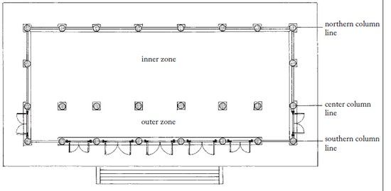
Figure 118 Plan of the
Sanzō-in Picture Hall.
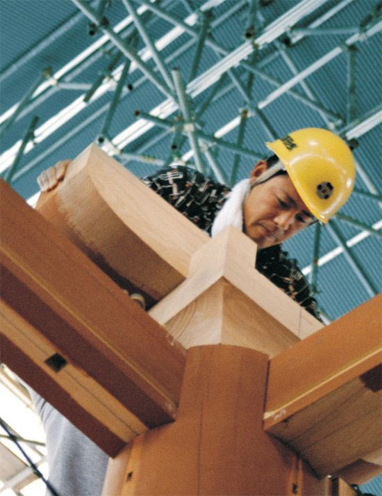
Figure 119 Placing a load-bearing block and cross arm on a column. (See Figs. 138, 139, 141.)

Figure 120 Southern elevation.
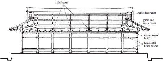
Figure 121 East–west section.
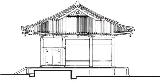
Figure 122 Eastern elevation.
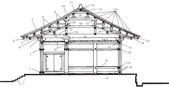
Figure 123 North–south section: 1. door sill; 2. mid-wall horizontal brace beam; 3. bracket complex; 4. wall purlin; 5. lower rafter; 6. upper rafter; 7. hidden rafters; 8. bridging; 9. stub posts; 10. mid-cross tie; 11. upper cross tie; 12. hidden ridge beam; 13. hidden ridge beam support block; 14. roof purlins; 15. eaves support; 16. upper rafter support; 17. head ties; 18. mid-wall penetrating tie beam; 19. waist tie beam; 20. base tie beam; 21. platform; 22. waist horizontal brace beam; 23. ceiling horizontal brace beam; 24. ceiling; 25. main beam; 26. outside longitudinal tie; 27. hidden support block; 28. post support block; 29. lower cross tie; 30. rafter hold-down beams; 31. upper longitudinal tie; 32. lower longitudinal tie; 33. ceiling lattice; 34. short main beam.
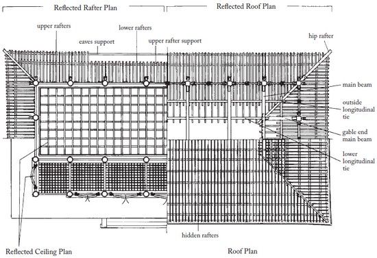
Figure 124 The reflected ceiling, rafter, and roof plans of Sanzō-in Picture Hall.
The assembly of the basic structure of the Picture Hall, including most of the roof, required only a month. Thereafter, the size of the crew was reduced and work proceeded more slowly, with the last of the roofing tiles laid in May 1986. Meanwhile, work had begun on the next building in the Sanzō-in compound, the Octagonal Hall, with only two carpenters remaining at the Picture Hall to work on the innumerable finishing details, such as the ceiling and doors. The building was essentially complete in January 1987, awaiting the interior wall paintings, tile floor, and other finishes.
During the construction of a building like the Picture Hall at Yakushiji, work proceeds simultaneously on several parts, complicating the task of documenting the various stages. The main beams may already be in place at one end of the building, while the bracket complexes are not yet installed at the other. Meanwhile, work goes ahead on the horizontal brace beams, the door sills, and even certain sections of the wall lattice. The following step-by-step explanation is given in logical sequence as far as the construction of the Picture Hall is concerned, but it does not necessarily adhere to strict chronological order.
FOUNDATION, PLATFORM, AND BASE STONES
The foundation of the Picture Hall is a heavily reinforced concrete platform set on footings 1.5 meters deep (Figs. 125, 128). Until modern times, foundations were simple stone-walled earthen podia into which were set large stones, one under each column. Today, largely for reasons of safety, modern foundation techniques are judged superior. Fortunately, the difference is undetectable to the eye.
When the Picture Hall was complete, the rough foundation was completely faced and paved in granite quarried in Hyogo prefecture (Figs. 220-222), except for the interior, which was tiled, but at the outset only the foundation stones were set. There are twenty-six foundation stones in all, each with a protruding bronze pin that fits into a corresponding hole in the base of the column (Figs. 130, 131). The bases of the columns themselves are slightly concave (Figs. 50, 129) to lessen the possibility of water being trapped beneath them and causing rot.
COLUMNS AND PENETRATING TIE BEAMS
Twenty columns form the perimeter, and six stand inside (Fig. 118). All are tied together by penetrating tie beams at four levels: at the base, at waist height, at mid-wall height, and at the head of the columns. The inner columns do not have base ties or waist height ties. For the perimeter columns, most of the base ties are trapped in notches at the extreme base end. Those spanning door bays are inserted a few inches above the floor, leaving a small space. Since the base ties rest directly on the foundation (Figs. 130, 131), they were laid out first and the columns then positioned above, temporarily supported by wooden blocks (all with the help of a small crane; Fig. 132). Mid-wall tie beams and door frames were inserted where necessary and secured lightly with wedges. Finally, the head tie beams were placed into slots at the uppermost ends of the columns. When a group of eight columns had been assembled, the blocks were gradually removed and the entire unit slowly lowered onto the foundation. The tie beams were more firmly wedged in, and the remaining columns and tie beams were added until the entire lower frame was complete. The erection process from the first column to the lower frame took four days.
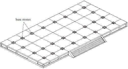
Figure 125 The Picture Hall
after installation of the foundation platform and column base
stones.
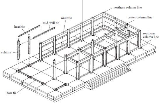
Figure 126 The Picture Hall with the lower frame nearly completed.
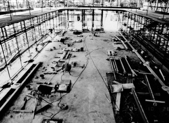
Figure 128 An overall view
of the site, with the column base stones in place.
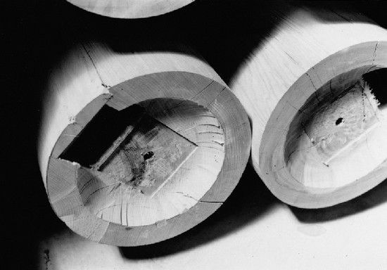
Figure 129 The bases of the columns are recessed to prevent the accumulation of water. The shallow square notch and center hole are designed to accommodate a bronze locating plate and a pin set on the foundation stone. (See also Figs. 50, 131.)
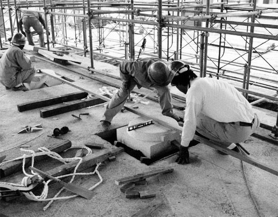
Figure 127 Masons positioning a base stone.
The uppermost tie beams, or head ties, were connected by splice joints located over the columns, taking advantage of the reinforcement provided by the surrounding slot (Figs. 133, 134). At the corners, they penetrated only partway into the column. The outer zone between the southern line of columns and the center line columns were also spanned by head ties, which required a 90 degree intersection.
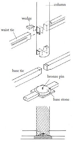
Figure 130 The configuration
at the base end of a column.
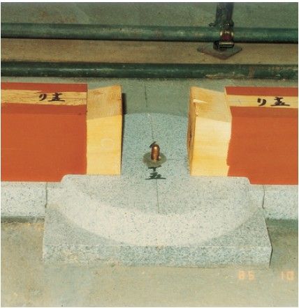
Figure 131
Base tie beams resting on the base stone. The bronze locating
pin for the column is visible at center.
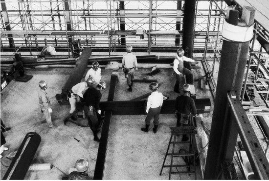
Figure 132 Mid-wall
penetrating tie beams were inserted into the columns on the ground,
and then raised as a section.
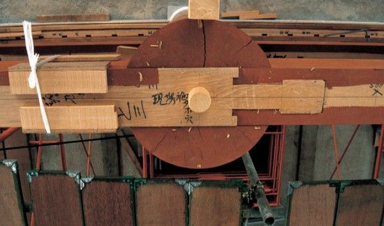
Figure 133 Square-headed
“gooseneck” splices were used on head tie beams where they joined
over columns.
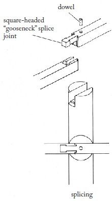
Figure 134 The relationship between head tie beams and columns.
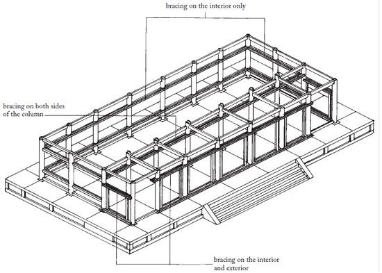
Figure 135 The Picture Hall
after installment of the bracing.
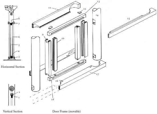
Figure 136 Door frame arrangement: 1. door post (movable); 2. door frame (movable); 3. door sill; 4. base tie; 5. door post; 6. door frame; 7. brace beam; 8. tie beam; 9. small tenons (top and bottom); 10. door post (stationary); 11. brace beam; 12. wedge; 13. tie beam (movable when wedge removed); 14. column; 15. brace beam; 16. small holes for door frame tenons; 17. door sill; 18. base tie (not movable). (See also Fig. 40.)
OUTSIDE HORIZONTAL BRACE BEAMS
Decorative horizontal braces were added above and below door openings on both the interior and the exterior, and at ceiling height, mid-wall tie height, and waist tie height on the interior (Figs. 135, 136). These braces have semicircular notches which fit around the columns. Each segment had to be fitted individually to the curves of the columns after the basic frame was erected. The brace beams are jointed and had to fit without gaps.
A special kind of brace beam was used at the bottom of the doorways (Fig. 137). As mentioned on page 71, the door sill was designed for easy replacement.
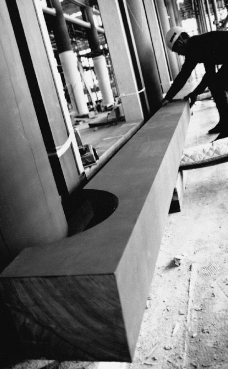
Figure 137 A door sill being installed.
BRACKET COMPLEXES
One bracket complex is located above each of the perimeter columns (Fig. 138). Altogether, there are fourteen regular, four corner, and two special bracket complexes (these last two are discussed in the next section). For each regular bracket complex (Figs. 139, 140), a large block was first fixed atop the column by means of a round dowel inserted into the head tie (Fig. 144). Next, a cross arm was added (Fig. 119), and then a center bracket arm, which rested on both the large block and the cross arm. Finally, two small blocks were placed atop the cross arm, situated on round pegs, to complete the bracket (Fig. 185).
The corner bracket sets were similar (Figs. 140, 142, 146), except that a tenon replaced the dowel and two cross arms were placed on top of the large block (Fig. 146). The center bracket arm was shaped to fit over the cross arms, ultimately nestling among four small blocks fixed by dowels to the two cross arms (Fig. 147). Short block-bearing struts were then put in place between each bracket complex (Fig. 130).
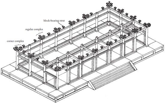
Figure 138 The Picture Hall after installation of the bracket complexes to support the roof load.
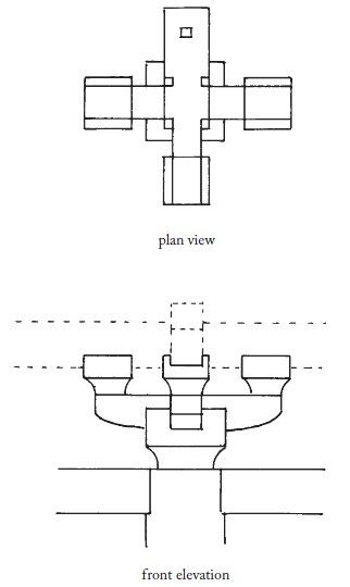
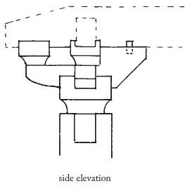
Figure 139 A regular bracket
complex.
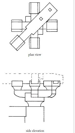
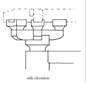
Figure 140 A corner bracket complex.

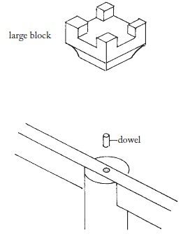
Figure 141 A regular bracket complex assembly.
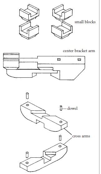
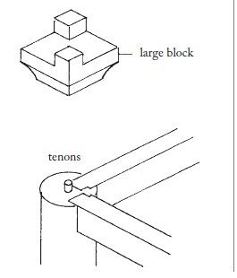
Figure 142 A corner bracket complex assembly.
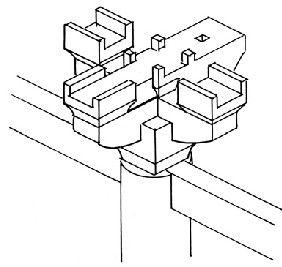
Figure 143 A completed regular bracket complex.
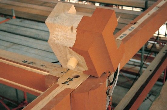
Figure 144 A large block is
located by means of a dowel inserted into the head tie beam over
the center line of the column.
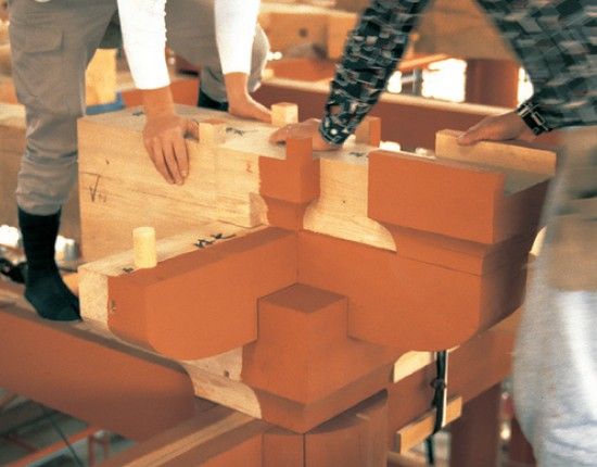
Figure 145 The center cross arm of a regular bracket complex fits over a smaller cross arm, both firmly supported by the large block.
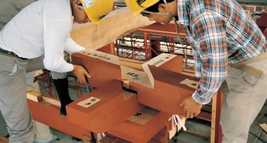
Figure 146 Installing the cross arms of a corner bracket complex.
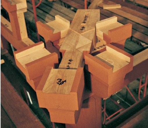
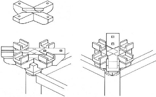
Figure 147 and Figure 148 A completed corner bracket complex.
BRACKET BEAMS
For reinforcement at the gable ends, two long beams with a bracket complex at one end span the center column line (Figs. 149, 152). At the bracket end (Figs. 150, 151), a projection penetrates a specially shaped large block and rests directly on top of the column. Together with the cross arm, this projection locks the beam in place (Fig. 153).
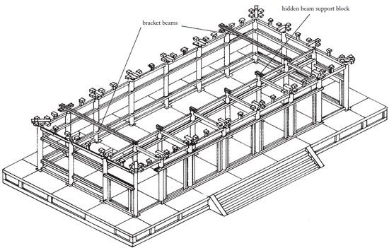
Figure 149 The Picture Hall after installation of the bracket beams.
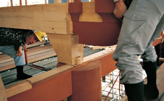
Figure 150 The bracket beam
has a projection that rests directly on the column and head tie
beam, snaring the dowel with a modified large block.
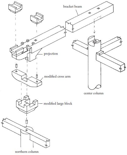
Fig. 151 The bracket end of a bracket beam.

Figure 152 Sectional view of
a bracket beam.
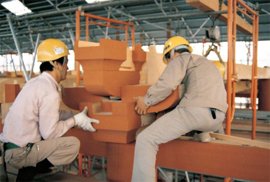
Figure 153 The modified large block and cross arm were designed to be inserted after the bracket beam had been put in place.
WALL PURLINS
The wall purlins tie the entire structure together at this level, resting atop bracket complexes and block-bearing struts (Fig. 154). Together with the penetrating ties and head ties, they define the wall plane (Fig. 123). The wall purlins are jointed into three sections on the long sides and two on the short, with the joints falling above the bracket complexes and the columns (Figs. 155, 160). The joints are designed to provide a smooth bearing surface for the members that will rest on them, and to resist both tension and torsion. The wall purlins overlap at the corners (Figs. 156, 159). Here we can begin to see the roof curve develop. As mentioned on page 70, while the head tie beams are perfectly horizontal, the wall purlins slope upward at the ends, supported by differences in height of the bracket sets and blocks.
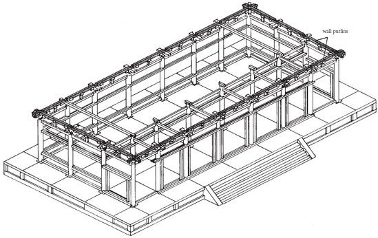
Figure 154 The Picture Hall after installation of the wall purlins.
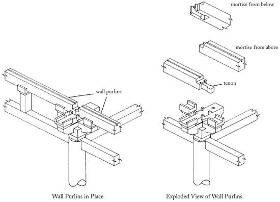
Figure 155 Wall purlins are spliced over the column and bracket sets with a variant of the “gooseneck” joint, leaving a recess and smooth surface on top to receive members above.
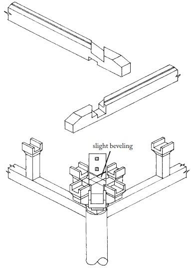
Figure 156 Wall purlins are joined at the corners with a simple cross-lap joint so as to accommodate the slope of the purlins as well as that of the members to be installed above.

Figure 157 The overlapping of wall purlins at a corner. Note the notch to receive the upper hip rafter.
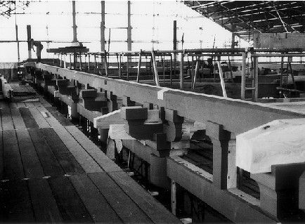
Figure 158 The slight upward
sweep of the wall purlins at the ends is perceptible in this
photograph.
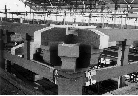
Figure 160 The modified “gooseneck” splice of wall purlins over a bracket complex.
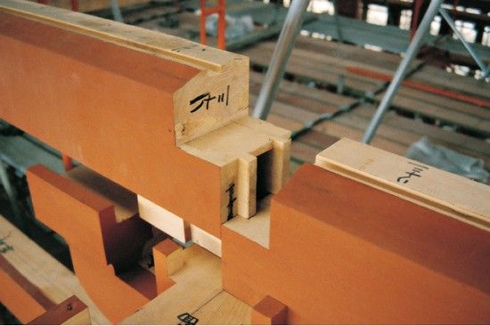
Figure 159 Wall purlins overlapping at the corner.
MAIN BEAMS
The next layer of the structure is composed of heavy main beams which span the structure crosswise, bearing most of the roof load (Figs. 161, 166). These beams are in two sections of different length, which join above the inner columns.
The shorter beams were installed first, with the help of a chain hoist. One end lay atop the block on an inner column, and the other end straddled the wall purlin situated as described earlier, resting on the bracket complex center arm (Figs. 162, 163, 165).
The longer beams were similarly installed, joined to the shorter ones with a zigzag splice joint (Fig. 164).
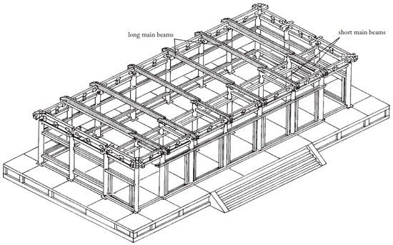
Figure 161 The Picture Hall after installation of the main beams.
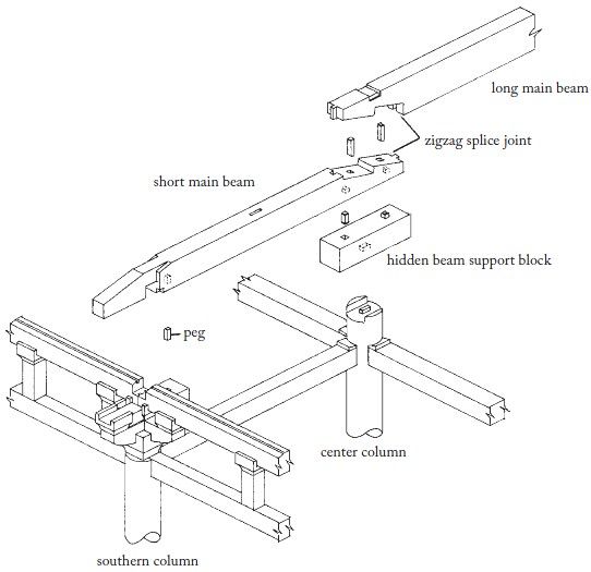
Figure 162 The main beam assembly.
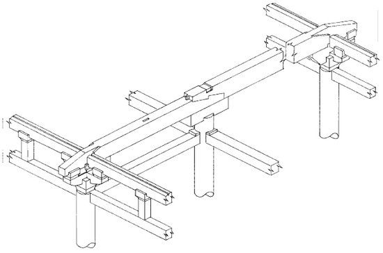
Figure 163 The completed assembly of the main beam.
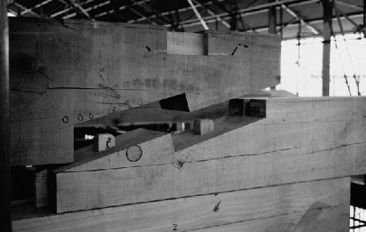
Figure 164 A zigzag splice
joint.
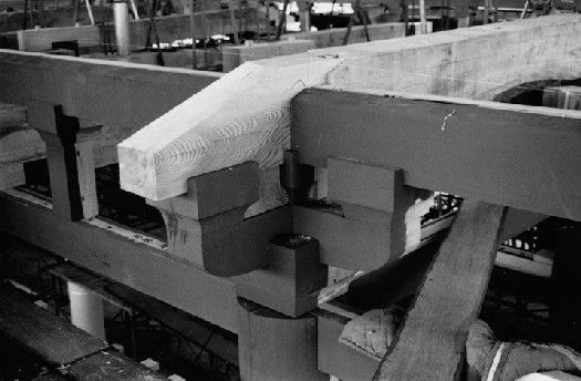
Figure 165 The long main
beams fit over the wall purlins and are supported by the center
arms of the bracket complexes. Thus, they lock the entire structure
together crosswise at this level.
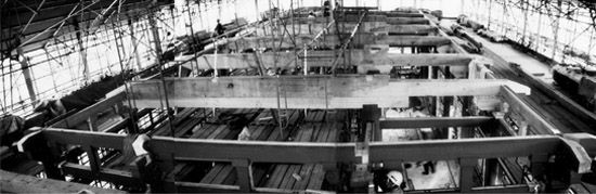
Figure 166 An overview showing the main beams in place.
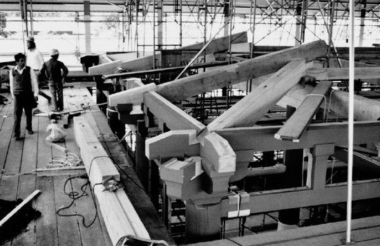
Figure 167 The corner main beams span at a slope from the nearest main beam to the corner bracket complex. The gable end main beams rest directly on the corner main beams and span to the exterior wall.
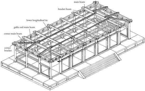
Figure 168 The Picture Hall after installation of the corner main beams, the gable end main beams, and the lower longitudinal ties.
CORNER MAIN BEAMS, GABLE END MAIN BEAMS, AND LOWER LONGITUDINAL TIES
Near the ends of the building, the long main beam rests directly on the long bracket beam, in effect becoming one extremely deep compound beam (Fig. 168). This is necessary because the weight of the entire roof at the gable end will eventually come to bear here, transmitted through the corner main beams and the gable end main beams.
Before the corner and gable end beams could be installed, however, the other main beams had to be tied together by means of long tie beams (lower longitudinal ties), which run almost the length of the structure. Like the head ties, these longitudinal ties are composed of jointed segments (Fig. 171) and sit in shallow notches on the upper sides of the main beams. They have mortises for short posts, which were added later.
The gable ends require a corner main beam, which spans from the corner bracket set to the doubled-up main beam nearby, sloping downward (Fig. 167). On top of it was placed the gable end main beam, which slopes even more steeply, spanning to a bracket set (Fig. 169). The result is a pile-up of structural members above the main beams, creating a giant knot of timber.
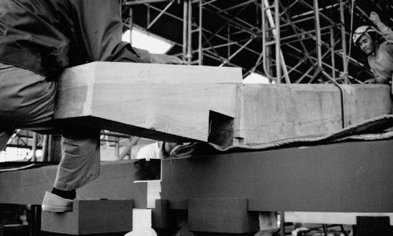
Figure 169 Like the other main beams, the gable end main beam was installed over the wall purlin and bracket complex. The carpenter at left has one foot resting on part of the bracket complex.
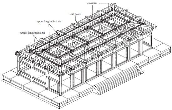
Figure 170 The Picture Hall after installation of the stub posts, outside and upper longitudinal ties, and cross ties.
STUB POSTS, OU TSIDE AND UPPER LONGITUDINAL TIES, AND CROSS TIES
Two more sets of longitudinal ties (the outside and upper) were installed here, supported on stub posts (Figs. 170, 174). They were then connected crosswise by cross ties. These ties were also connected at the gable ends. The structure above an inner column at this point is as shown in Fig. 173.
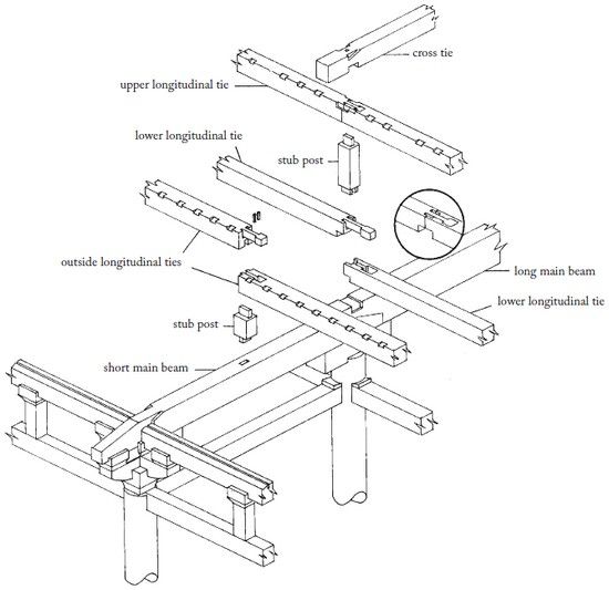
Figure 171 Assembly of the stub posts, longitudinal ties, and cross ties.
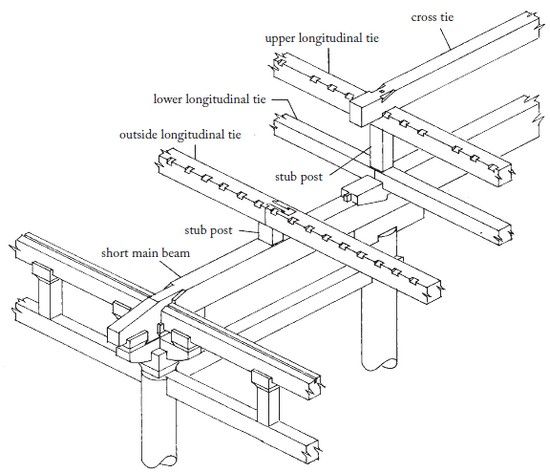
Figure 172 The completed assembly of the stub posts, longitudinal ties, and cross ties.
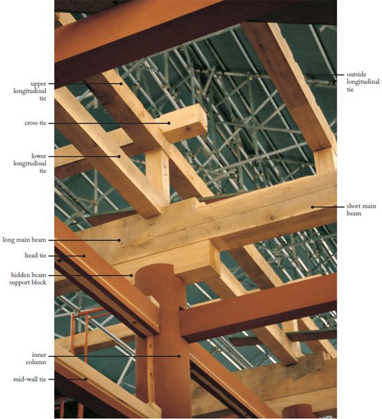
Figure 173 The structure
above a typical inner column.
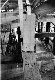
Figure 174 This stub post is located over a “gooseneck” splice joint in the longitudinal tie. Double tenons were used to straddle the “gooseneck” tenon below.
HIP RAFTERS
Hip rafters are composed of two parts, a lower (or “base”) part and an upper (or “flying”) part. They cantilever outward beyond the wall line almost a third of their length and bear a significant portion of the overhanging roof load (Fig. 175). The lower hip rafter fits into slots at three points: where the outside and upper longitudinal ties overlap, on the corner main beam, and where the wall purlin and the corner bracket set come together (Figs. 176, 167). Hip rafters are shaped so as to lock these several layers of structure together while being supported by them.
The lower hip rafters required painstaking installation as the ends of all four had to lie exactly level to each other. Any discrepancies among the numerous supporting members had to be resolved at this stage through careful trimming and adjustment, complicated by their great weight (Figs. 179, 181). Once the lower hip rafter was in position, the upper portion could be simply installed, kept in place by a long groove and two rectangular pegs (Figs. 182, 183). The parts were eventually permanently jointed by large U-shaped wrought-iron clamping pins, but were left unconnected throughout the fitting of the rafters and rafter supports described in the next section.
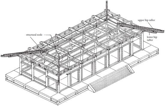
Figure 175 The Picture Hall after installation of the hip rafters.
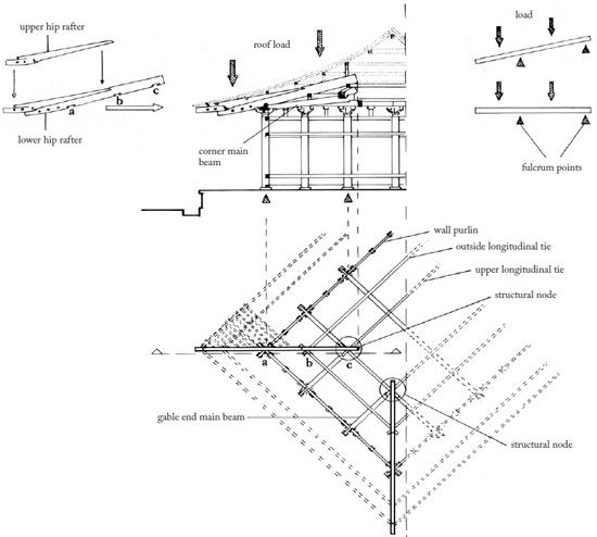
Figure 176 Hip rafter function. A hip rafter is notched onto a wall purlin at a, onto the outside longitudinal tie at b, and onto the upper longitudinal tie at c.
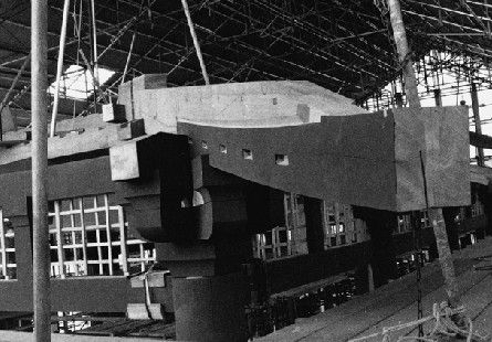
Figure 177 This lower hip
rafter extends past a corner bracket complex.

Figure 178 The upper hip rafter as it was installed.
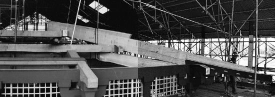
Figure 179 A lower hip
rafter.
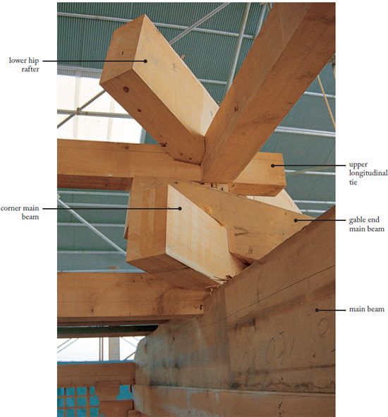
Figure 180 The structural node where the beams and hip rafter meet.
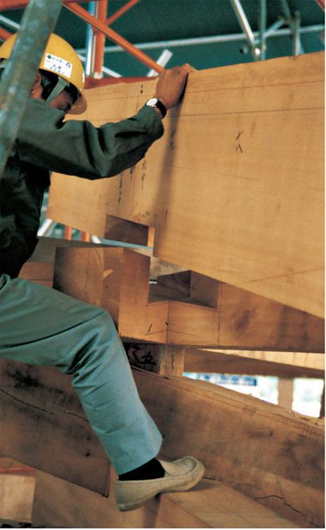
Figure 181 The fit of a
lower hip rafter is repeatedly tested and trimmed if
necessary.
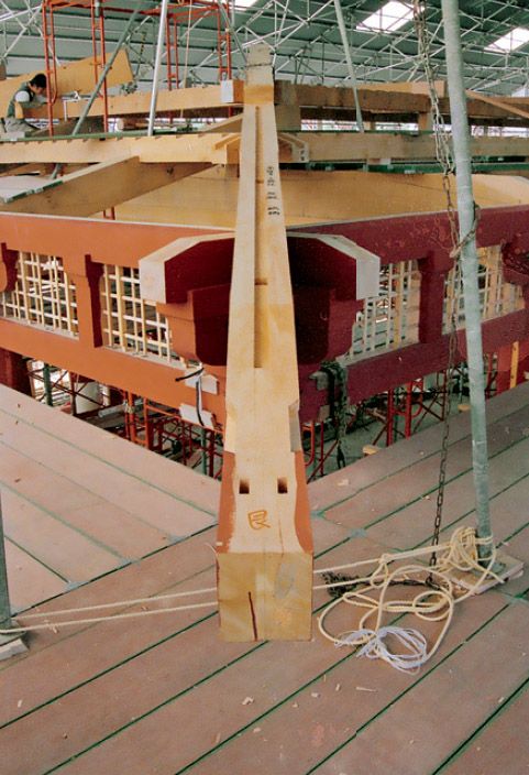
Figure 182 The upper hip rafter will be mated to the lower hip rafter by means of square pegs and a long tongue-and-groove. (See also Fig. 183.)
LOWER RAF TERS AND UPPER RAF TER SUPPORTS
The lower rafters lie across the outside and upper longitudinal ties and the wall purlins (Fig. 187). Like the hip rafters, they cantilever out about two meters. The lower rafters nestle into toothlike slots on the longitudinal ties and into toothed boards set into a slot in the wall purlins. At their extreme ends, they support a toothed beam which, in turn, supports the upper rafters (Figs. 185, 186). This beam, or upper rafter support, is made in sections. The rafters which support the joints were the first to be installed, their heights adjusted until the support beam was perfectly curved. (The upper rafter supports are curved in both plan and elevation, that is, they twist upward and outward as they approach their intersection with the hip rafters; page 70). Once the proper curve was established, the remaining lower rafters were installed and sandwiched into place at their upper ends by a hold-down beam. The rafters at the corner intersect with and are connected to the hip rafters, and so are shorter than the rest. Other rafters run alongside the main beams, and come in contact with the bracket sets. The rafters were then secured in place with large wrought-iron spikes.
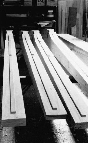
Figure 183 Upper hip rafters upside down, each showing the long tongue which fits into a corresponding groove in the lower hip rafter. (See Fig. 182.)
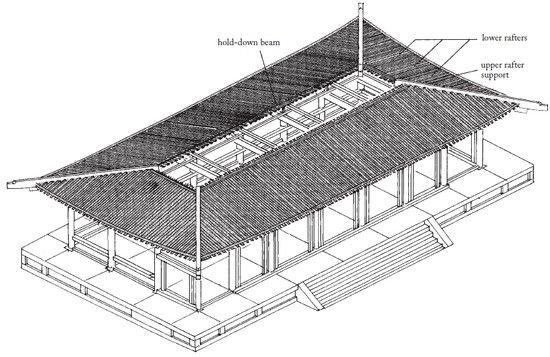
Figure 184 The Picture Hall after installation of the lower rafters and upper rafter supports.
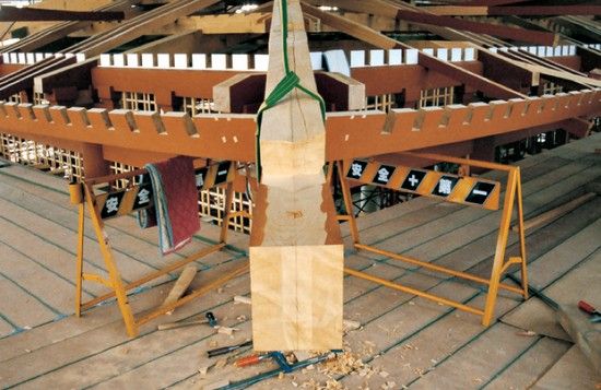
Figure 185 The upper rafter
supports are themselves supported at the ends by the hip rafters.
Their curve is very pronounced in both plan and section. (See also
Fig. 67.)
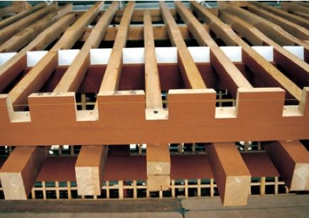
Figure 186 The toothed upper
rafter support is attached to the lower rafters by means of
wrought-iron spikes.
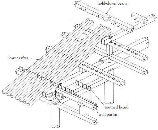
Figure 187 Assembly of the lower rafters and upper rafter supports.
UPPER RAF TERS AND EAVES SUPPORTS
Before the upper rafters could be installed (Fig. 188), a layer of backing boards had to be placed over the lower rafters (Fig. 189). These were painted white on the underside and spanned the gaps between the rafters, one board for each opening. They were positioned so as to allow for expansion. The upper rafters were then inserted into the toothed slots in the upper rafter support, with their other tapered ends resting on the lower rafter backing boards. The upper rafters supported a curved beam similar to the upper rafter support called the eaves support (Fig. 190). The eaves support fills the gap between the upper rafters and the roofing tiles, and receives the lower ends of another layer of sheathing. A special joint was used to connect its segments. This beam was installed similarly to the upper rafter support, that is, with the jointed areas being supported and adjusted first. With the installation of the remaining rafters, the exposed underside portion of the roof was complete.
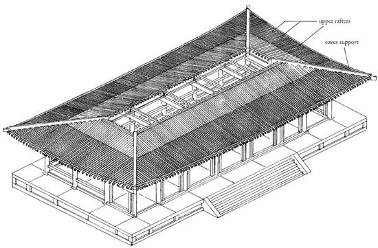
Figure 188 The Picture Hall after installation of the upper rafters and eaves supports.
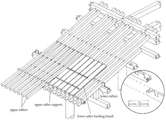
Figure 189 Assembly of the
upper rafters and eaves supports. The inset shows a dovetail splice
joint on an upper rafter support.
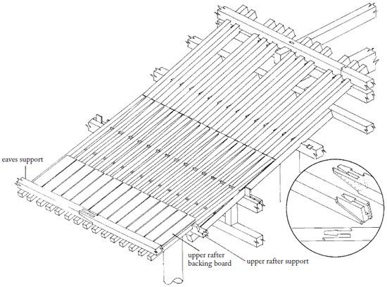
Figure 190 Assembly of the upper rafter backing boards and eaves support. The inset shows a splice joint on an eaves support.

Figure 191 The cantilever
action of the rafters.
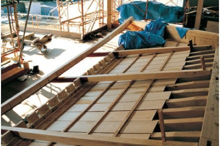
Figure 192 The upper rafters
in relation to the upper rafter support and eaves
support.
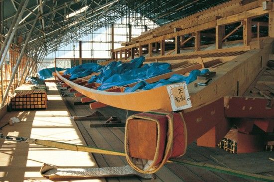
Figure 193 The eaves support.
HIDDEN ROOF STRUTS AND BEAMS
One design feature that separates Japanese temples from their continental prototypes is the use of an illusion in the roof area. The rafters that are exposed at the eaves are not the “real” rafters in that they do not directly support the roof surface. The slope of the actual roof is steeper than indicated by the members exposed at the eaves. Thus, Japanese temples are said to have a “hidden” roof. In effect, a hollow space is formed between the gently sloping exposed rafters and the steeply sloping hidden rafters. This hollow space is filled with stub posts and roof purlins, and numerous small braces, or bridging (Fig. 194). The actual rafters rest atop the purlins and are entirely hidden from view.
To install the hidden rafters, stub posts were first inserted into mortises in the rafter hold-down beams, of which there were six sets in all (Fig. 195). These stub posts increase in height as they approach the roof ridge, and all of them have slots for bridging. Near the top of the roof, another set of cross ties was installed, resting on blocks set atop the stub posts (Fig. 196). Two more sets of posts were inserted into the cross ties, followed by two more roof purlins. This was followed by the installation of another set of cross ties, and finally the blocks which support the hidden ridge beam itself. In addition, the decorative purlins, which were to be left exposed at the gables, were installed (Figs. 199, 200).
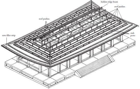
Figure 194 The Picture Hall after installation of hidden roof structure (rafters and bridging omitted for clarity).
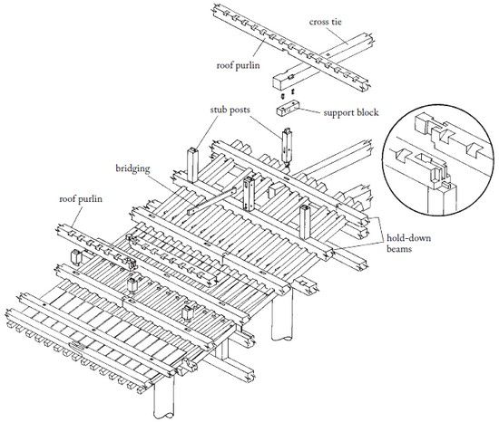
Figure 195 Parts of the hidden roof structure. The inset shows a square-headed “gooseneck” splice in the roof purlin.
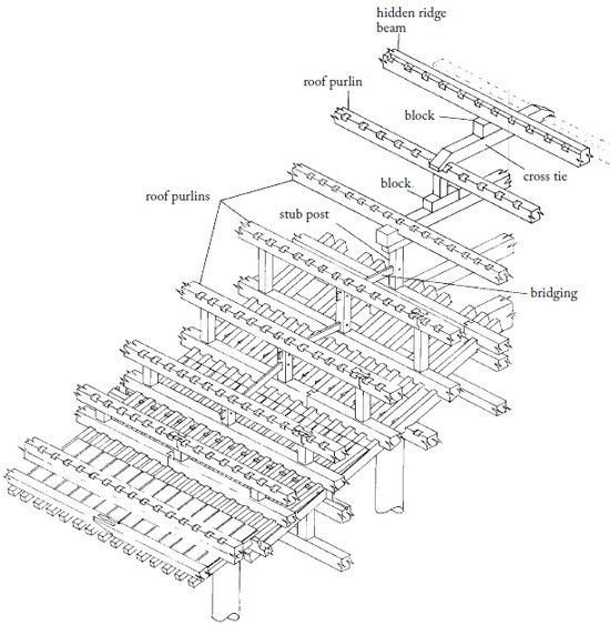
Figure 196 The hidden roof members and the ridge beam in place.
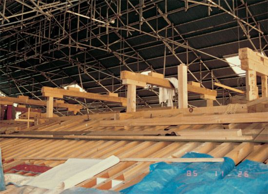
Figure 197 The uppermost roof purlins and stub posts are installed.
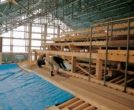
Figure 198 The mid-cross
ties are carried on short blocks on top of the uppermost stub
posts.

Figure 199 The hidden ridge
beam is uppermost. Below it are the short decorative beams that
will be visible at the gable.

Figure 200 The hidden ridge beam, with the decorative ridge beam below it.
FINISHING THE ROOF STRUCTURE
The hidden rafters now had to be installed above the roof purlins (Figs. 201-204). They are noticeably smaller in section than the exposed rafters and had to be bent to accommodate the roof curve. Roofing boards (sheathing) were then laid above the hidden rafters. The gables, which would be left exposed, were completed by the addition of fascia boards, a decorative set of cross beams, struts, and diagonal braces (Fig. 205), rafters, and a decorative pendant.
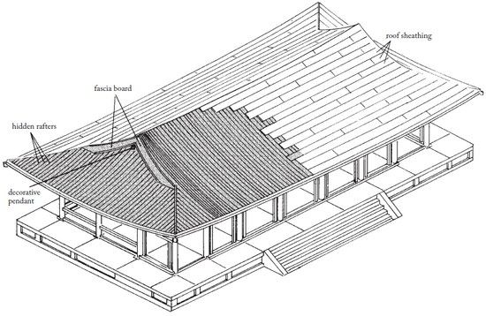
Figure 201 The Picture Hall after the installation of the hidden rafters and sheathing.

Figure 202 The completed
hidden rafter structure. The inset shows a detail of the edge of
the eaves: 1. eaves support; 2. eaves filler strip; 3. tiles; 4.
hidden rafter; 5. roof purlin; 6. hold-down beam; 7. upper rafter
support.
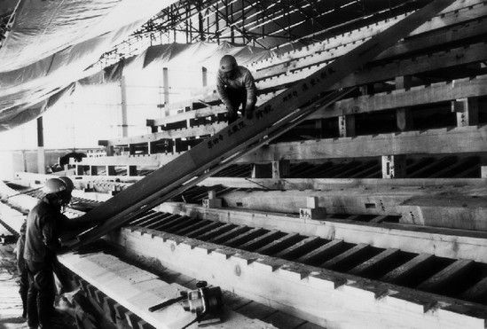
Fig. 203 Since the curve of the hidden rafters will define the visible roof line, they are carefully placed with the use of a template.
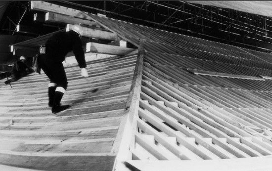
Figure 204 The hidden rafters (visible on the right) are being covered with sheathing boards.
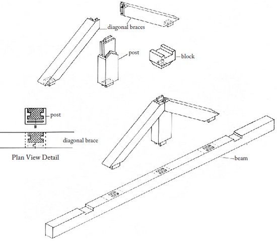
Figure 205 A decorative beam and a strut for a gable. (See also Figs. 57, 70, 210.)
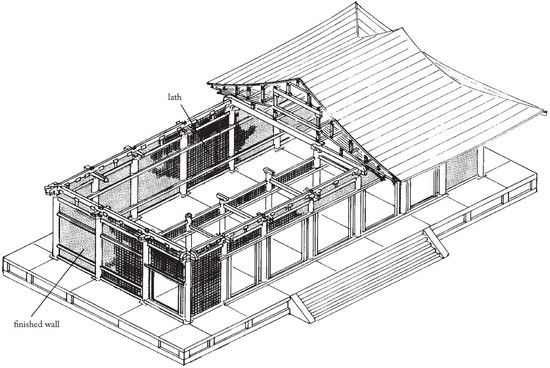
Figure 206 The Picture Hall in the process of wall installation.
WATTLE AND DAUB WALLS
Lath for the clay walls was installed all around the building (Fig. 206). It consisted of a lattice of thin wooden members, which were inserted in shallow mortises in the columns and beams, and wrapped with rope (Figs. 207, 208). This formed a base to which the plaster, a mixture of clay and straw, which had been allowed to ferment for several months, would adhere securely. The clay plaster was applied in several layers of slightly different formulation and allowed to dry thoroughly between coats. The clay layers were applied by hand and the surface coats, a fire-resistant mixture which contained lime, by trowel, which was then polished (Figs. 209-211). The final wall was a hard, gleaming white (Fig. 33).
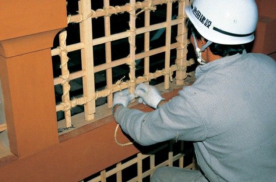
Figure 207 Lath was
installed as a grid of thin wooden strips wrapped with hemp
rope.
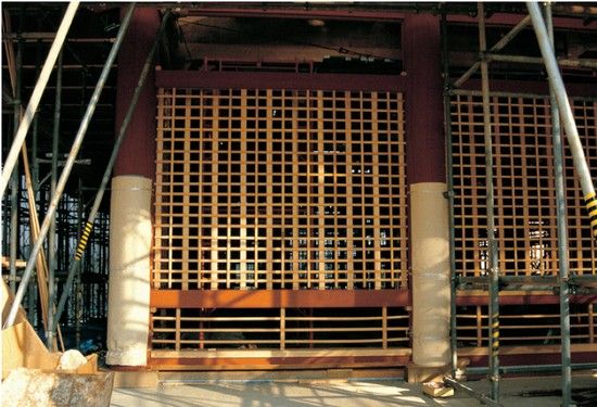
Figure 208 The nearly completed latticework on the western wall.

Figure 209 Clay plaster
after being applied to one side of the wall.

Figure 210 The gable end after the rough coats of plaster have been applied. The straw, which is used to strengthen the plaster and prevent it from cracking, is clearly visible. The wall was later finished with several coats of hard white plaster. (See Fig. 33.)

Figure 211 Final coats are troweled on, creating a progressively smoother surface.
CEILING
The ceiling of the Picture Hall is a jointed wooden lattice (Figs. 212-214) into which painted boards have been placed. It fits into the penetrating tie beams at the perimeter, and is supported over the center span by suspension rods attached to the roof structure. The grid over the outer zone is smaller than that over the inner zone and is noticeably lower. Hatchways were provided for access.
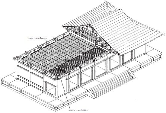
Figure 212 The Picture Hall after installation of the ceiling lattice.

Figure 213 Positioning the ceiling members.
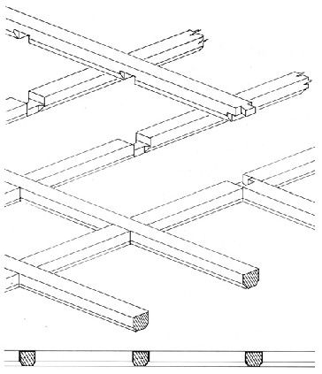
Figure 214 The ceiling is a
grid of wooden members (approximately 10 cm square in section),
which are jointed at every intersection.
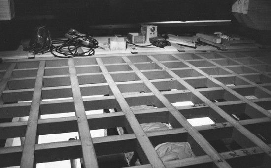
Figure 215 Over the outer zone, no suspension rods are required because of the relatively short span.
EXTERIOR DETAILS
The doors were among the last elements to be added (Figs. 216-219). There are five doorways across the front, and one at each side, positioned to connect with the surrounding corridor. Each doorway has a pair of doors. An individual door has five wooden parts: three thick panels (tongue-and-grooved) and two rails (upper and lower), which lock the panels together. The doors are decorated with thick gilt-bronze strap hardware.
The concrete foundation was completely faced and paved in granite (Figs. 220-222). The facing was applied in a conventional manner, with adhesive mortar and metal straps embedded in the concrete. The paving was laid in a simple pattern, cut on the site to accommodate the column base stones. Mortar was applied dry, leveled, and then wet with a ladle. The stone was positioned with the help of small shims which ensured even spacing, and more water was applied and allowed to enter the cracks. The stone was tapped with a rubber mallet until perfectly level.
All of the rafters received pierced-work bronze plates on their ends (Figs. 4, 223, 224). Bronze bells were hung from the hip rafters, and bronze bosses were applied to conceal spike heads on the outside horizontal brace beams.
The exterior walls were plastered white (Fig. 33), awaiting the paintings which were to be applied to the interior walls and the ceiling, along with a warm-colored natural tile floor.
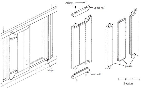
Figure 216 Door assembly. Each door is fabricated from three solid planks, locked together by upper and lower rails.
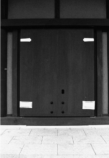
Figure 217 The finished
doors are almost airtight.
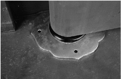
Figure 218 Smooth pivot
hinges of gilt bronze.
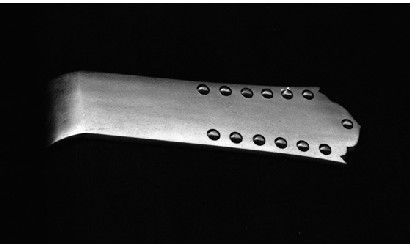
Figure 219 Thick gilt-bronze
strapping echoes the traditional hung hinge.
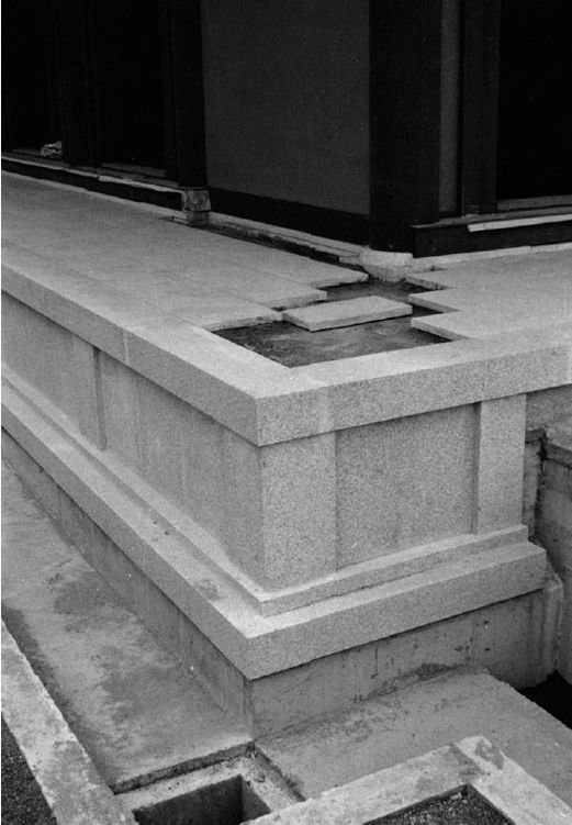
Figure 220 Granite facing
and paving stones were among the last details to be
added.
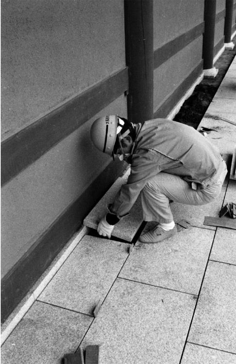
Figure 221 The paving stones were set in a thick bed of mortar.
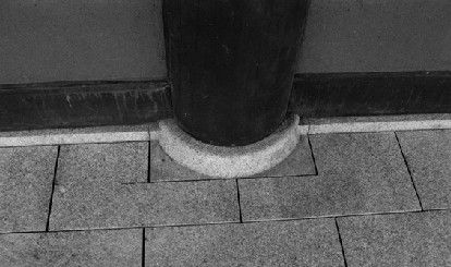
Figure 222 A detail of the paving stones and column base stone.

Figure 223 The gilt-bronze
plates are both protective and decorative, and highlight the
structural rhythm of the rafters.

Figure 224 Applying gilt-bronze pierced-work rafter end caps.
ROOF TILES
Traditionally, Japanese architecture uses several types of roof tiling systems. The buildings at Yakushiji used a silver-gray tile manufactured nearby, with a decorative pattern taken from the original eighth-century pagoda. This roof required tiles of several different shapes.
The primary tiles are slightly dished rectangles and these were placed in rows side to side, with the upper tiles overlapping the lower ones (Figs. 227-231). Their joint lines were covered with semi-cylindrical tiles, which overlapped the tiles on either side (Figs. 232-234).
All of the roof ridges were covered by stacked rectangular tiles, crown side up, which were in turn capped by the semi-cylindrical tiles. Large decorative “ogre” tiles and bird perch tiles terminated these groups of tiles (Fig. 238).
Before the modern era, the space between the curve of the roof sheathing and the tiles was often filled with clay, which made the curve of the roof smooth and provided a secure bed for the tiles. At Yakushiji, considerable weight was saved by laying the tiles on wooden battens, fastened in crucial places by nails and copper ties. (Figs. 226, 227, 241). The resultant seal was equally as watertight as the traditional method.

Figure 225 The finished Picture Hall after the laying of tiles.

Figure 226 A layer of cedar
bark was applied over the roof sheathing boards, and then a set of
battens was laid horizontally.
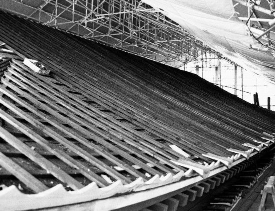
Figure 227 Another set of
battens was laid vertically, and a scalloped tile cant strip was
added.
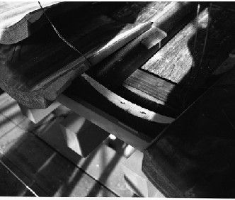
Figure 228 The primary eave
tiles, which are decorated at the end, were the first to be laid,
fastened with wire ties to the vertical battens.
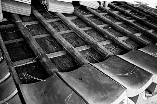
Figure 229 The remaining
dished primary tiles were applied row by row.
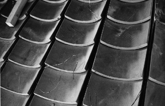
Figure 230 A small gap was left between adjacent rows of primary tiles.
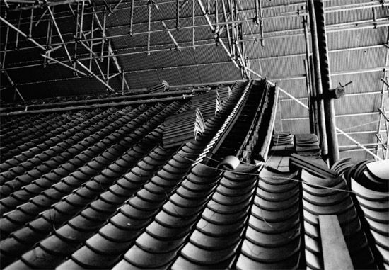
Figure 231 The roof after
all the primary tiles had been laid.
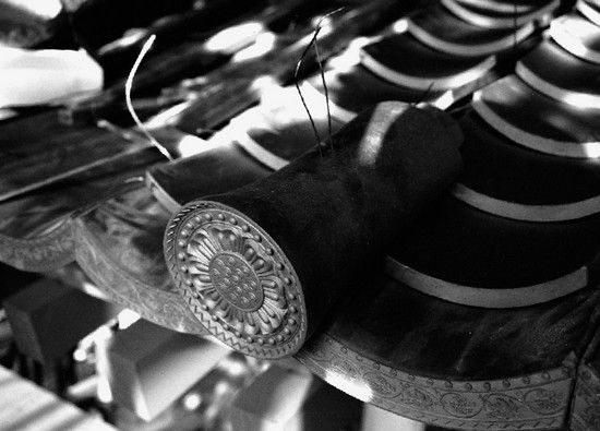
Figure 232 The gap between
the primary tiles was covered by semi-cylindrical tiles. Those at
the eaves are decorated.

Figure 233 The
semi-cylindrical tiles were laid so that upper tiles overlapped
lower.
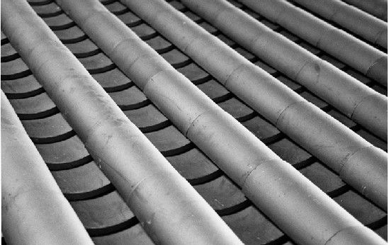
Figure 234 Semi-cylindrical
tiles in place.
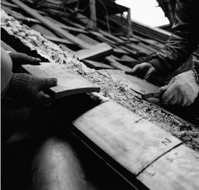
Figure 235 Ridges were formed by stacked, slightly convex tiles set in mortar.
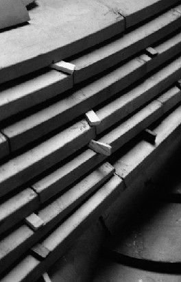
Figure 236 The ridge tiles
were held in place with small wooden spacers until the mortar had
set.
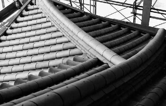
Figure 237 The ridges were
capped with semi-cylindrical tiles. Angled intersections were
covered with specially shaped tiles.
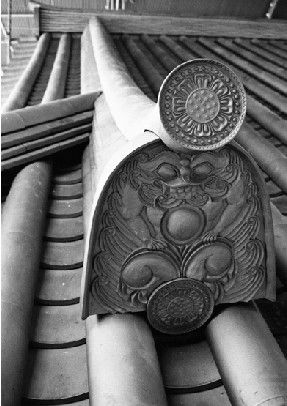
Figure 238 The ends of the
ridges, flaring upward, were capped with decorative “ogre” tiles as
well as a modified cylindrical tile called a “bird
perch.”

Figure 239 The cylindrical
end tiles, like this one at the peak of the gable edge, have a
decorative motif based on the lotus blossom, in a particular
pattern associated with Yakushiji since its inception.
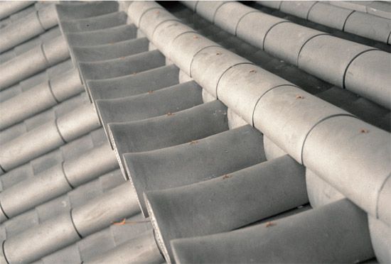
Figure 240 The scale and
rhythm of the tiles may have its roots in archaic roofs made of
bamboo.
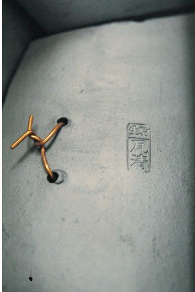
Figure 241 The tiles are stamped with a maker’s mark. Those in certain locations were tied to the structure beneath with thick copper wire.