CHAPTER 9
MAKING
A JOINT
During the early periods of civilization in both Europe and Asia, the connection of wooden structural elements posed a great technological challenge. Throughout the world, Stone Age people usually met this challenge by lashing timbers together with strong fibers such as vine or strips of tough bark. As stone tools developed, primitive joints were fashioned by gouging out holes for the insertion of roughly shaped tenons. With the advent of bronze tools, and later iron, wood joinery attained forms familiar even to us today, and experimentation led to the invention of splices, intersections, dovetails, and means of joining flat panels. In Western civilization, the Egyptians (as seen in their surviving wooden furniture) and the Greeks (as seen in their roof structures) are known to have possessed advanced wood joinery techniques. The Romans developed these further, building complex wooden geared water wheels, arched wooden centering for the construction of vaults and domes, and complex catapults and other machines of war. Most of these woodworking techniques were never entirely lost, surviving in Arab countries and reappearing in late Medieval Europe. Western wood joinery reached another peak in Tudor England, where it was often used in church spires and other monumental structures. Later, English emigrants to America took with them a highly advanced repertoire of joinery techniques, most of which survived there, as in Europe, until the late nineteenth century. It is interesting to note that during this entire period, the economic viability of wood joinery depended upon its low cost relative to other means of connection—metal fasteners such as bolts, nails, and the like—which had existed since the earliest eras but were often prohibitively expensive. In the West, this situation changed rapidly with the Industrial Revolution, when both cheaply milled lumber and mass-produced nails became common. By the early twentieth century, architectural wood joinery had virtually disappeared.
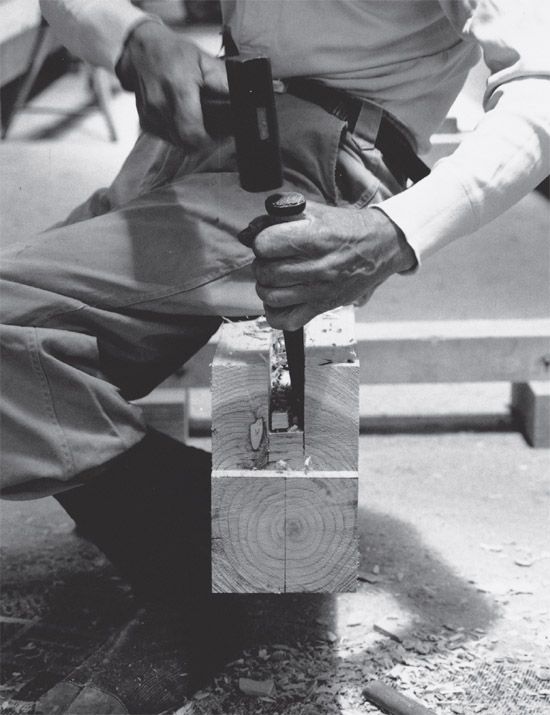
Figure 89 Skill at wood joinery sets Japanese carpenters apart from others.
In Asia, the situation was somewhat different. It may be argued that even in the millennium before Christ, Chinese joinery techniques were more advanced than their Western counterparts. Although dynasties changed frequently, there was a cultural continuity in all fields in China unmatched in European culture, reaching one peak during the Han dynasty (ad 0–200) and another during the Tang (ad 600–900). The complex joinery practiced by Japanese carpenters during the building of early temples like Yakushiji represents the state of the art in early Tang China, as distilled once by contemporary Koreans and again by builders on Japanese soil. Exactly how many of the early Japanese temple builders were native Japanese is open to debate. Nishioka believed that because Hōryūji temple was based on an ancient Korean shaku scale, and Yakushiji on a Chinese scale, their master carpenters may have been Korean and Chinese respectively.
The joinery seen in Japan today thus represents the survival of an extremely archaic way of building, a kind of living time capsule. Nishioka also believed that the ancient carpenters were incomparably better than modern-day artisans, and yet, to this day, advanced joinery can be found throughout Japan. Most houses, when constructed in wood, feature traditional joints reinforced with hardware, thanks partly to newly developed computer-assisted milling machines that mass-produce jointed timber frames. Nevertheless, all agree that the days of joinery are numbered. Prefabricated housing and two-by-four construction have proven to be economical, efficient alternatives.
Many of the techniques used in temple joinery can be demonstrated in the fabrication of a basic end joint or splice, in this case the half-lapped “gooseneck” joint, one of whose functions is to connect sections of a roof purlin (Figs. 90-177).
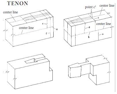
Figure 90 Half-lapped “gooseneck” splice joint. Top: Joint laid out. Bottom: Completed mortise and tenon.
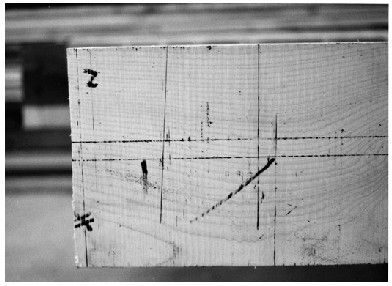

Figure 91 and Figure 92 The joint is first laid out on the end of the timber. The most important line is the center line. The other dimensions are standardized and can be quickly laid out with a steel square.

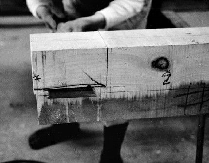
Figure 93 and Figure 94 The waste wood below the tenon is removed with a saw, first crosscutting (Fig. 92) and then ripping (Fig. 93). In both cases, the cut is taken right to line a and b (Fig. 89).
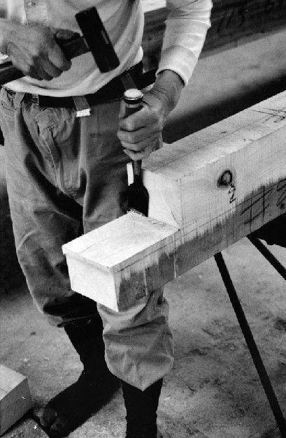
Figure 95 The waste is knocked out with a hammer, and the inner corner cleaned up with a chisel.
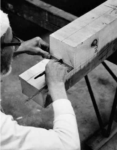
Figure 96 The underside of the tenon is laid out on the freshly cut surface with a steel square and bamboo marking pen.
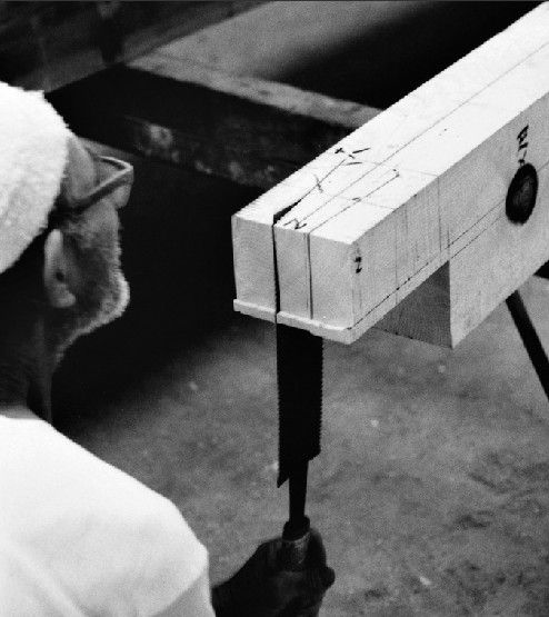
Figure 97 The angled surfaces of the tenon are sawed, extending the line all the way to cheek line c.
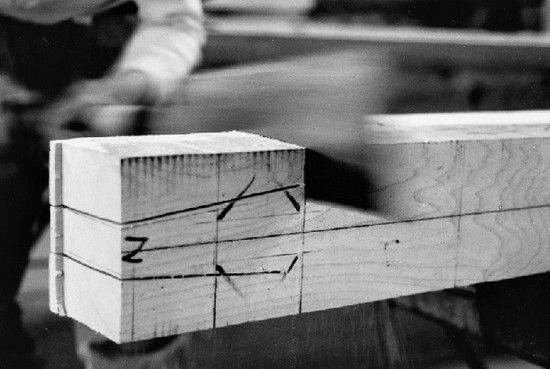
Figure 98 The cheeks are sawed all the way to the points marked c1, and the waste removed.
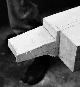
Figure 99 Line d, which defines the head, is laid out. It is actually a bevel that serves to draw the joint tight as it is inserted.
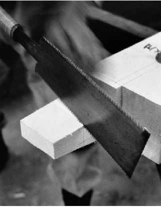
Figure 100 The tip is trimmed to the line, and the bevel line d is cut. This is repeated on both sides.
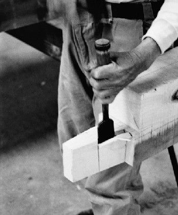
Figure 101 The waste is chopped out with a chisel.
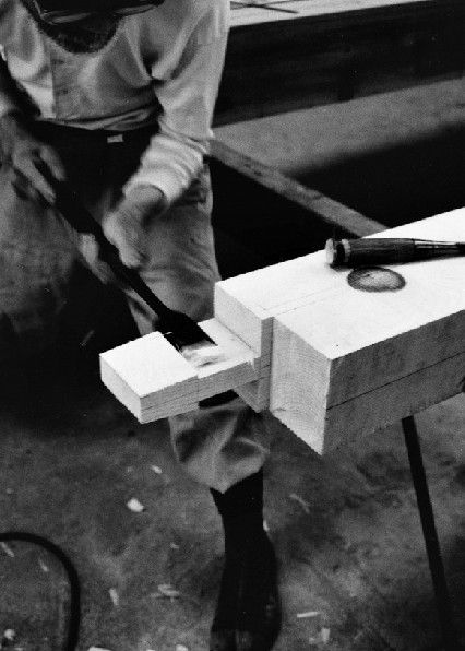
Figure 102 The surface is smoothed with a slick.
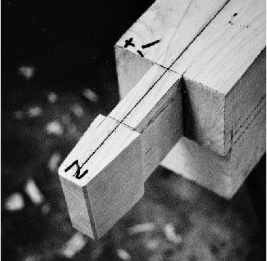
Figure 103 The finished tenon.
MORTISE
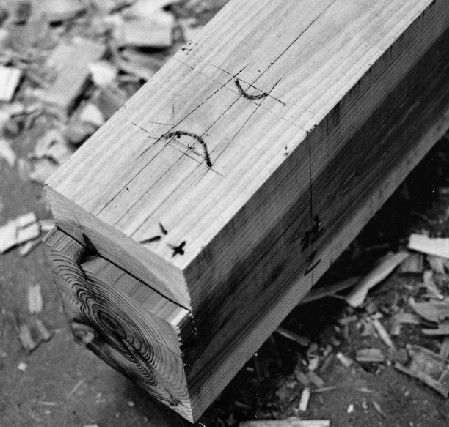
Figure 104 The mortise is aid out. (See also Fig. 89.)
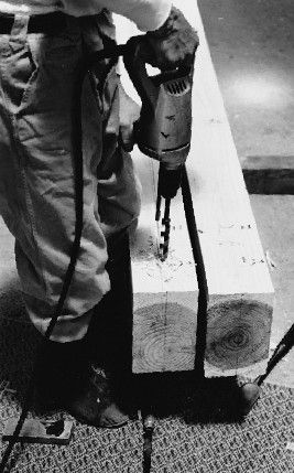
Figure 105 The mortise is first drilled to remove as much waste as possible.
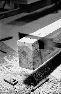
Figure 106 The lap at the end is cut with a saw, first crosscutting at lines e and f and then ripping along line g.
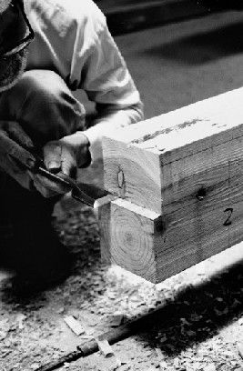
Figure 107 The waste is knocked out, and the inner edge trimmed with a chisel.

Figure 108 The mortise is laid out on the freshly cut vertical face.
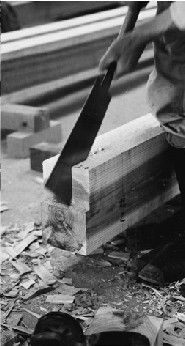
Figure 109 The mortise sides are cut with a ripsaw as far as possible.
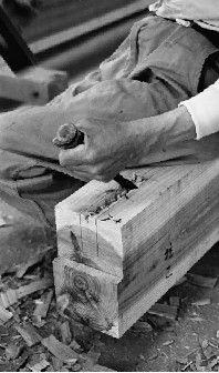
Figure 110 The mortise is chopped out with a chisel at an angle.
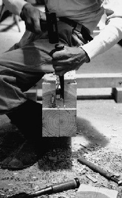
Figure 111 The mortise is chopped vertically.
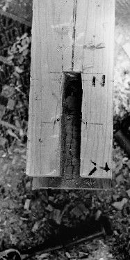
Figure 112 At this point, a parallel-sided mortise is obtained.
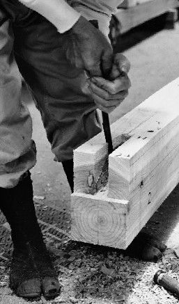
Figure 113 The beveled line for the head of the tenon is laid out inside the mortise and then sawed.
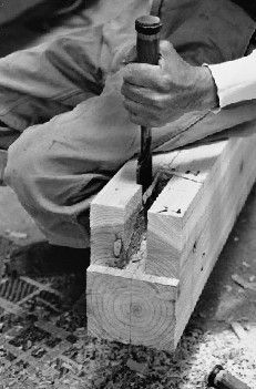
Figure 114 The waste is chopped out with a chisel.
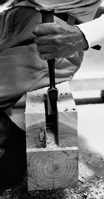
Figure 115 The line is then trued.
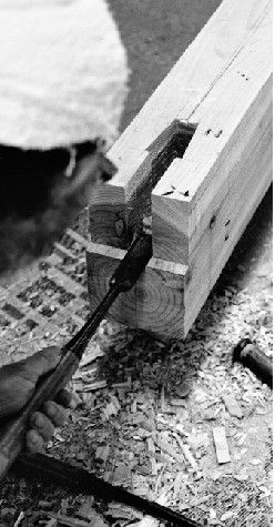
Figure 116 Lastly, the inner faces are smoothed with a slick, and the bottom surface given a slight incline to ease insertion. The surrounding edge of the opening on the upper face is also beveled slightly.
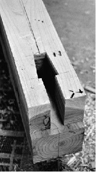
Figure 117 The finished mortise.