5.4 The Seed Sensor
A photocell measures light intensity, with higher intensity correlating with higher current and lower intensity with lower current. For a more detailed explanation and tutorial on photocells, visit Ladyada’s ever-helpful website.[47] By placing the photocells at a level beneath the seeds poured into the feeder, we can detect when the seed level dips below the sensor, exposing it to more light and thereby alerting us that the feeder needs to be refilled.
Before drilling holes into the feeder for placement of the photocell, we need to write some code and test it using the same approach that we did for our homemade foil resistor.
Connect one of the photocell leads to the Arduino 5v pin and connect the other photocell lead to the Arduino analog pin 0. Then bridge a 10k ohm resistor between the Arduino analog pin 0 and the Arduino ground pin, as shown in Figure 13, Wiring diagram for the photocell test. Does this electrical pattern look familiar? Yep, it’s the same wiring configuration used previously with Arduino sensors in this book. This is a frequent pattern for various types of sensors that connect with the Arduino.
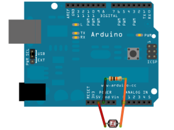
Figure 13. Wiring diagram for the photocell test
With the photocell connected, connect the Arduino to the computer via the USB serial cable and launch the Arduino IDE. Using the same technique used for the foil switch, monitor analog pin 0 values in the Arduino IDE’s serial monitor window and capture baseline values for when the sensor is bathed in ambient, standard lighting conditions. Then cover the sensor with your finger to block incoming light. Note the difference in value.
Just as we did for the capacitive test, we will write the same type of procedures and conditional statements to test for luminosity thresholds. Indeed, you could copy and paste code from the foil test and simply change variable names and connected pin assignments to create the working program.
| TweetingBirdFeeder/SeedPhotocellTest.pde | |
#define
SEED 500 |
|
#define
ONBOARD_LED 13 |
|
#define
PHOTOCELL_SENSOR 0 |
|
int
seed_value = 0; |
|
byte
seed_state = 0; |
|
void
setup() |
|
{ |
|
// for serial window
debugging |
|
Serial.begin(9600); |
|
|
|
// set pin for onboard led |
|
pinMode(ONBOARD_LED, OUTPUT); |
|
} |
|
|
|
void
SendSeedAlert(int seed_value,
int seed_state) |
|
{ |
|
digitalWrite(ONBOARD_LED, seed_state ? HIGH : LOW); |
|
if (seed_state) |
|
Serial.print("Refill seed,
seed_value="); |
|
else |
|
Serial.print("Seed refilled,
seed_value="); |
|
Serial.println(seed_value); |
|
} |
|
|
|
void
loop() { |
|
// wait a second each loop
iteration |
|
delay(1000); |
|
|
|
// poll photocell value for
seeds |
|
seed_value = analogRead(PHOTOCELL_SENSOR); |
|
|
|
switch (seed_state) |
|
{ |
|
case 0: // bird
feeder seed filled |
|
if (seed_value >=
SEED) |
|
{ |
|
seed_state = 1; |
|
SendSeedAlert(seed_value, seed_state); |
|
} |
|
break; |
|
|
|
case 1: // bird
feeder seed empty |
|
if (seed_value <
SEED) |
|
{ |
|
seed_state = 0; |
|
SendSeedAlert(seed_value, seed_state); |
|
} |
|
break; |
|
} |
|
} |
|
Measuring and assigning the defined SEED threshold value for the photocell is much
easier and more reliable than the capacitive foil test we did
earlier. While you can use your finger to cover up the photocell
and measure the value change, it is more authentic to test with
real seed. If you don’t want to drill holes in your bird feeder to
set the photocell just yet, use a paper cup and place the photocell
toward the bottom of the cup.
Similar to the calibration procedure we used in the
Water Level Notifier project, add these lines after the
seed_value =
analogRead(PHOTOCELL_SENSOR); request in the sketch’s main
program loop:
Serial.print("seed_value="); |
|
Serial.println(seed_value); |
Record the seed_value
starting value, then fill the cup with seed and measure the new
value. Use these values to set the starting and threshold values
for the photocell.
If you do not see any change, check your wiring and try again. In my tests with the photocell, the baseline value fluctuated between 450 and 550. It reported below 100 when my finger covered the sensor. Use whatever upper and lower limit values you recorded with your tests, keeping in mind that they will need to be recalibrated once the sensor is mounted inside the feeder.
Now that monitoring is working for both the perch and light sensors, we need a way to communicate when those sensor thresholds have been exceeded. It’s not very practical to run an Ethernet cable from an indoor network hub to an outdoor tree limb. Not to mention that trying to fit a bulky Arduino+Ethernet shield assembly into the confined space of a bird feeder would be a challenge. We will use the convenience of low-power wireless communication to transmit these sensor notifications to an indoor computer. Then we will use that computer’s faster processing and larger storage capacity to analyze and act upon the data received.