3.3 Hooking It Up
Let’s start by making sure our flex sensor works the way we intend it to. Connect the positive lead of the sensor to the Arduino’s 5.0-volt pin using a wire. When looking at the flex sensor standing on its end, the positive lead is the trace that runs vertically. The negative lead is the one that looks like the rungs of a ladder. Connect the negative lead to the analog 0 pin with another wire. Lastly, bridge the analog 0 pin to the ground pin using the 10k ohm resistor to dampen the flow of current through the circuit. Refer to Figure 3, Water Level Notifier wiring diagram, to make sure you attach the wires and resistor to the correct pins.
Attach the bobber to the end of the flex sensor. Most bobbers come with a retractable hook that can be fastened to the plastic tip of the sensor. If the bobber doesn’t stay affixed to the sensor, you can also use hot glue or heat shrink tubing to help keep the bobber attached. Just be careful not to damage the sensor when heating it with these affixing solutions. You can also try duct tape as a safe alternative, though the tape may lose its grip over time.
Use plenty of wire so you have enough length to safely mount the Arduino and power source far away from the water source. The Arduino that I have monitoring my sump pit is sitting in a hobby box mounted on the wall several feel above the sump pit, and the two wires attached to the flex resistor are about two meters (roughly six feet) in length.
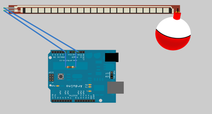
Figure 3. Water Level Notifier wiring diagram
Now that the Arduino has been wired up, we can work on the logic of what the hardware is supposed to do for us. We will begin with a quick test program that will verify that the flex sensor is connected correctly and working properly.