CHAPTER TWELVE
Ventilation
Ventilation in UK housing and in passivhaus, indoor air quality (IAQ), humidity, mechanical ventilation with heat recovery (MVHR) (components, heating, efficiency, noise levels, possible objections to MVHR, installation skills)
Every new or retrofit building requires a considered ventilation strategy. The basic principle is to ensure that indoor air is being refreshed regularly, although the benefits of achieving a good ventilation strategy are multiple – from avoiding mould growth to limiting airborne pollutants. The quality of the air will also affect how comfortable we feel – too hot, too cold, too dry, etc. Some effects of a poor ventilation strategy, such as cold draughts, overly dry air or noisy extraction fans, will always be noticeable. But it is also important to be aware that we are not always able to assess air quality with our own senses. Bad odours can be very unpleasant, but are often harmless, while more serious health issues relating to ventilation could well go unnoticed.
If you are commissioning or are part of a team delivering an ultra-low-energy building, you must be confident that your ventilation strategy will be effective. The Passivhaus standard adopts a ‘mixed-mode’ ventilation strategy, comprising a mechanical ventilation system, which includes heat recovery from the exhaust air (energy that would otherwise be wasted to the outside), and summer ventilation/cooling using openable windows. This combined approach is an integral and essential part of Passivhaus low-energy design and is considered part of the quality standard of a Passivhaus building. It has been adopted not only to address functional needs but is also part of the comfort standard.
Our experience is that a Passivhaus home will effectively extend the seasons in which you feel thermally comfortable with open windows – so you are likely to still be opening your windows after your non-Passivhaus neighbour has shut theirs. Because a Passivhaus is so airtight, even with open windows it retains its heat for longer than a conventional house, and in the shoulder seasons it will be getting significant solar gain.
Ventilation strategies in UK housing
Historically, buildings have been so ‘leaky’ that there is more than sufficient ventilation for occupants by default. Resultant draughts have been exacerbated by the common use of open fires, which further draw in cold external air in order to feed the combustion process. The traditional design of the high-backed ‘wing’ chair was adopted to provide shelter from this draught while seated facing the open fire. Up until the 1970s, people were content to live at much lower temperatures and would dress accordingly: in winter you simply wore lots of layers.
Typical housing in the UK from the 1920s onwards would be built using a cavity wall construction, consisting of two separate leaves of brickwork (later the inner leaf was changed to concrete blocks). About 80 per cent of existing housing is estimated to be of cavity construction. Cavity insulation started from around the 1970s, and, with the introduction of insulation standards, recent new housing stock does provide some improved thermal performance. However, this is still far below what a low-carbon economy would require. Only in 2006 was a statutory value set for maximum air leakage. This figure – a maximum air permeability of 10m³/hr/m² at 50Pa (see Chapter 9) – is not demanding and we doubt many new houses would fail this requirement. Currently, the typical airtightness level achieved is an air permeability of around 7m³/hr/m² at 50Pa. Conventional methods for ensuring adequate ventilation in the UK generally take the form of trickle ventilators in windows (often left in the closed position because people are not aware of what they are) combined with localised mechanical extraction from bathrooms (usually on timers, often noisy and sometimes disabled by the disgruntled) and the kitchen (generally via a kitchen cooker hood extracting to the outside). Such mechanical extraction clearly helps to remove smells and moisture at source, and to reduce condensation risks. However, it does not generally involve any heat recovery from the extracted warm, moist air.
Low-energy design necessarily moves us towards designing less leaky buildings. This minimises energy loss to the outside, improves insulation performance and reduces moisture ingress into the building fabric. The current airtightness target in the UK for a zero-carbon house is a maximum air permeability of 3m³/hr/m² at 50Pa – a target that still allows the use of natural ventilation strategies, i.e. openable vents or windows (without any mechanical assistance) and reliance on naturally occurring pressure differences to move the air through the internal rooms. Often the air will be vented out at a high level, since warmer air naturally rises, so the staler air might perhaps exit at the top of a staircase, for example. Of course, adopting natural ventilation solutions carries with it an energy penalty, and this has to be reflected in the energy targets set for space heating for such houses. The zero carbon standard requires 39-46kWh/m² per year for space heating (depending on house type) – more than treble the Passivhaus standard (see Chapter 5, page 67). However, this would still be extremely low compared with the average performance achieved by current new UK housing.
Passivhaus ventilation – a mixed-mode strategy
The Passivhaus ‘mixed-mode’ ventilation strategy ensures that there is always a continuous supply of fresh air even when windows are closed. This enables the Passivhaus air leakage target of 0.6ach (air changes per hour) at 50Pa – the lowest of any building standard in the world. A common misconception about Passivhaus is that windows are physically non-openable or that you are not allowed to open them! This is not the case, and in summer the whole house can be ventilated naturally, just like any other house. In fact, a Passivhaus should be designed so that air can naturally flow through the building. As we saw in Chapter 11, openable windows can also be used effectively at night to cool down the building in the hotter summer months; this, combined with high insulation levels and appropriate window shading, is a core strategy for keeping low-energy houses cool. In fact, the PHI requires at least one openable window per room.
The mechanical ventilation with heat recovery system, or MVHR, is also sometimes referred to as comfort ventilation or heat recovery ventilation (HRV). MVHR units are not heat pumps and contain no refrigerants, which is another common misconception. MVHR systems simply handle incoming and outgoing air.
MVHR is a ‘whole-house’ ventilation system, with fresh air delivered to all the habitable spaces (bedrooms and living areas) and extracted from the wetter/smellier rooms in the house (bathrooms, toilets and kitchens). The air circulates naturally and gently from these supply zones to the extract zones, so that the whole house is continually being refreshed with clean, filtered outside air.
The heat recovery element of the ventilation strategy is key to Passivhaus, in that the incoming air is preheated by the extracted air. The extracted air is not mixed with the incoming air; the two air flows are separated by a thin plate with a large surface area through which the heat is transferred, in what is called a counter-flow heat exchange chamber (see Figure 12.1 opposite). In a Passivhaus the MVHR system is designed to ensure that the minimum temperature of the air delivered into any room is 16.5°C when the outside air temperature is -10°C.
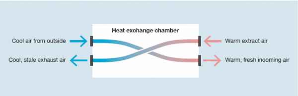
Figure 12.1 Recovery of heat in an MVHR heat exchange chamber.
In addition to ‘recapturing’ energy that would otherwise be wasted, this pre-warming of the supply air provides a level of user comfort, since it eliminates cold draughts. Cold draughts make us feel less comfortable (the wind-chill factor) and we tend to want to increase the ambient room temperature to compensate. With pre-warming of the incoming air, an average occupant will feel as comfortable with the room temperature set two degrees lower than in a conventional building.
Ventilation and indoor air quality (IAQ)
There are relatively few academic studies on air quality within the home, which is surprising given that such a high percentage of an average person’s time is spent indoors. A typical person in industrialised countries such as the UK and US now spends 90 per cent of their time indoors. In these societies there is also a worrying increase in the number of people suffering from asthma – the UK and US have the highest levels of sufferers in the world. The possible connection between this and the rising use of chemical products in the materials, finishes and furnishings of our homes and buildings is commonly alluded to (as is a possible link between asthma and outdoor pollutants, e.g. from traffic). If there are grounds for making this connection with indoor allergens – and many argue that there are – then the introduction of continuous and controlled air supply must be of benefit. If this approach is combined with the use of natural materials and finishes and/or materials that emit low levels of volatile organic compounds (VOCs), such as concrete, linoleum, wood, ceramics, lime, clay and natural paints, then air quality must be improved. Using more natural cleaning products will also contribute to lowering VOC levels. Even without an absolute proven connection with health conditions, organisations such as the US Environmental Protection Agency (EPA) recognise that poor IAQ is a prominent environmental problem, with a related health penalty for society to pay. The US LEED standard dedicates a whole section to IAQ, mostly limited to discussion of materials and finishes, with minimal reference to ventilation strategies. In order to ensure good IAQ, both these aspects need to be considered.
Since buildings will become increasingly airtight in the future, the risk of poorer IAQ must be a serious consideration. Some people have been interested in using low-embodied-energy, locally sourced and natural materials, and have built eco-houses without necessarily attempting to build leak-free constructions. This approach will certainly have improved air quality without the use of typical ventilation strategies (i.e. trickle vents in windows and bathroom extraction fans). However, if your intention is to build a low-energy (in use) house, then the ventilation strategy becomes critical.
Passivhaus ventilation and indoor air quality (IAQ)
Measuring carbon dioxide (CO2) levels in the indoor air is considered an acceptable indicator of air quality, since CO2 levels reflect indoor air pollutant levels. Air quality is classified according to the European Standard EN 13779, with four levels set at different CO2 concentrations, from IDA 1 (high quality) to IDA 4 (low quality). IDA 2 (medium quality – 400-600ppm [parts per million] of CO2) is considered to be good air quality. Both ASHRAE (an international research/ standards organisation dealing with ventilation) and the US Occupational Safety and Health Administration (OSHA) set a maximum indoor CO2 level of 1000ppm. This compares with typical outdoor levels of 350-450ppm. People start to complain about stuffiness and odours as levels rise above 600ppm (IDA 3 is 600-1000ppm – moderate quality), and drowsiness kicks in as they rise above 1000ppm (IDA 4). There is a useful study of carbon dioxide levels relating to a Passivhaus retrofit of a block of flats in the Marbachshöhe area of Kassel in Germany.1 It compares winter CO2 levels in a standard bedroom in the original building, which relied on natural ventilation, with a bedroom in the Passivhaus retrofit, which relied on MVHR. The resultant measurements of CO2 (see Figures 12.2 and 12.3 opposite) show the levels regularly rising above 1500ppm in the old bedroom while remaining comfortably below 1000ppm in the Passivhaus, mainly within level IDA 2. Figure 12.2 clearly shows that opening windows will quickly purge any stale air, but once they are closed the CO2 levels rise again quite rapidly. The bedroom in the old building has particularly poor air quality during the night. A second study compared Austrian low-energy housing, relying on natural ventilation, with comparable Passivhaus units.2 Here both had acceptable air-quality results (although the Passivhaus was more energy efficient), and the MVHR-ventilated units had lower CO2 concentrations, in particular during cold periods and especially in multiple-occupancy apartments.
The Passivhaus approach is often applied to school buildings in parts of Europe, e.g. all new school buildings in Frankfurt must now be built to the standard. The first Passivhaus school in the UK is now open in Exeter. Part of the motivation for adopting the Passivhaus standard for schools is air quality, which is known to improve concentration and learning capacity.
The PHI has calculated that the IDA 2 standard will be met by an airflow rate of approximately 30m³/hr per person – the level recommended by the PHI, and the default assumed in the PHPP.
Automating the MVHR – CO2 sensors
In a house with large daily or weekly variations in the number of occupants, it is possible to link the MVHR unit to a CO2 sensor that will vary the air change rate the MVHR unit delivers according to need. This is a standard approach in non-domestic buildings and could also be used in tenanted residential buildings.
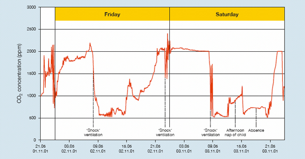
Figure 12.2 Levels of CO2 in
an apartment using opening windows as the ventilation strategy.
Adapted from: Passivhaus Institut (PHI) 2001/2. CEPHEUS:
‘Measurements and evaluation of Passive House apartment buildings
in the Marbachshöhe neighbourhood of Kassel, Germany’
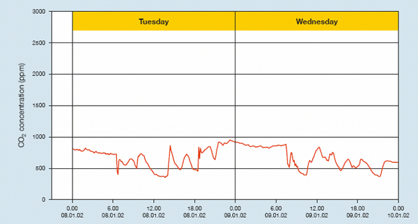
Figure 12.3 Levels of CO2 in
an apartment using MVHR as the ventilation strategy.
Adapted from: Passivhaus Institut (PHI) 2001/2, as above
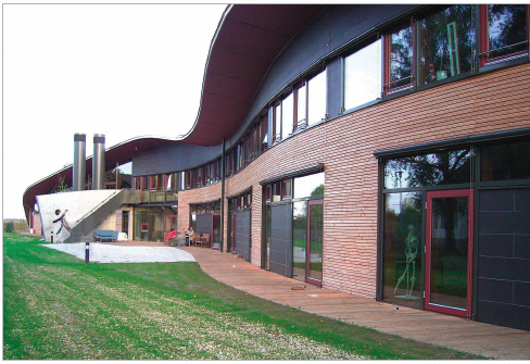
Montessori school in Aufkirchen, Germany, built to the Passivhaus standard. Image: Passivhaus Institut
There is also a PHI-recommended air change rate of 0.3ach at normal air pressure. This is set to avoid the risk of low air humidity in the winter (dry air), which reflects the climate conditions in Germany.
Indoor air quality (IAQ) and relative humidity (RH)
Relative humidity levels are also a factor in maintaining comfortable air conditions for occupants. Air needs to be neither uncomfortably humid nor uncomfortably dry. The RH target should be between 35 and 55 per cent: 30 per cent is considered very dry air, while 70-80 per cent is very humid – at both these levels there are implications for health (see Figure 10.2, Chapter 10, page 149).
The amount of water vapour that can be contained or carried in the air is relative to its temperature (hence the term ‘relative humidity’). We are sensitive to humidity levels because our bodies use evaporative cooling to regulate our temperature. The rate of evaporation of our perspiration changes depending on the RH, so we may feel cooler or warmer at the same air temperature. In warm, humid weather, the rate of evaporation slows, so we will feel much hotter than in warm, arid conditions. Once air reaches 100-per-cent RH, the air is ‘saturated’ and condensation will occur.
Dry air
Drier air can be an irritant to a building’s occupants, and tends to exacerbate respiratory diseases. If external fresh air contains too little moisture (say, on a very cold winter’s day), it is useful to be able to modify the delivered internal air quality by setting the MVHR to a lower airflow rate (i.e. the PHI-recommended minimum of 0.3ach). If the external air is already dry, then the MVHR can exacerbate this (warming the air also dries it!). The Passivhaus standard originated in a climate that tends towards drier winter air conditions, and for this reason the PHI advises against the oversupply of fresh air, recommending that airflow should not be increased unnecessarily. In such conditions, drying clothes inside your building can be useful, to add moisture back into the air.
In very cold, dry climates it is also possible to install membranes that will allow the exchange of moisture from the extract air into the supply air. In the USA, ventilation in low-energy housing is delivered by entropy recovery ventilation (ERV), now often referred to as energy recovery ventilation, which includes this moisture-exchange function. These systems are used where there is either high humidity or very low humidity levels.
Humid air
If, on the other hand, the air becomes too humid, dust mites proliferate, the risk of mould growth increases, and bacteria and viruses can flourish. A maritime climate such as in the UK tends to higher humidity levels, and in these conditions it may be useful to set the MVHR to slightly higher airflow rates (for a target air change rate of perhaps 0.35-0.4ach).
There are also other useful mechanisms for modifying moisture levels. Indoor plants, for example, are great natural humidity modifiers. It is also worth thinking about the choice of surface materials in the house, and considering those that can readily absorb moisture from the air and then release it back in a cyclical process. Hygroscopic materials, such as natural clay and lime plasters, will hold and then release water vapour cyclically into the surrounding atmosphere, and can also permanently absorb some VOCs. This dynamic ‘hygric’ (moisture-related) response will keep the RH more stable, helping to avoid surface condensation or mould growth. The quality of the air experienced in rooms with clay-plastered walls is often commented on by those inhabiting them. There are academic studies that demonstrate the effectiveness of using vapour-open and hygroscopic materials, which most definitely help to improve IAQ when used as part of a holistic approach to ventilation. We would encourage this approach. Remember that the initial moisture levels in a new build will be affected by the moisture within the structure itself, and it may take some time before the building fully dries out (a minimum of two seasons, i.e. years). Moisture levels will also be determined by the form of construction; some techniques involve more water than others.
Monitoring internal RH levels in Passivhaus homes built in a maritime climate (using humidity/temperature data loggers) would be a useful exercise, both in terms of building up a data resource and for the purposes of furthering optimisation of the overall ventilation strategy in any given building.
Humid air, mould growth and ventilation
Condensation forms on surfaces where the air is carrying high levels of water vapour (See Figure 10.1, Chapter 10, page 148). This, combined with low surface temperatures, may eventually lead to mould growth. Often this can occur where air is not being regularly refreshed (mould in room corners, behind furniture or in built-in cupboards is common). Moisture arises from human breathing/sweating, cooking, washing, plants, etc., and occupational behaviour can exacerbate potential mould problems – for example, keeping windows closed, not using bathroom extractor fans (in conventional houses), and drying wet clothes over radiators. With the trend towards higher internal temperatures in our homes, mould growth is not an uncommon problem. However, providing continuous background ventilation (both air supply and air extraction) alleviates most of these risks. The Passivhaus approach of continuous insulation, minimal air leakage and triple-glazed windows further ensures that the internal surface temperatures, even at window panes, do not fall below 17°C. This not only eliminates surface condensation but also contributes to avoiding convection-driven draughts.
On retrofit projects, be aware that once air leakage is radically reduced, air humidity will rise – with an increased risk of surface condensation unless a ventilation strategy is in place. Any area that is not insulated to a good level may then be vulnerable to mould growth. This risk is addressed as part of the EnerPHit standard (see Chapter 1, page 30).
Mechanical ventilation with heat recovery (MVHR)
A Passivhaus is designed so that the MVHR system can provide all the ventilation needs during the winter months, when most people generally do not want windows open. The MVHR system will usually achieve an air change rate of 0.3-0.4ach under normal conditions. As already noted, the PHPP software recommends an airflow rate provided by the ventilation system of 30m³/hr per person as a design standard. The design default for a typical house assumes 35m² of treated floor area (TFA) per person. This may not reflect a larger house or very small flat, so the PHPP should be modified to reflect these circumstances (see Chapter 7, page 93).
The MVHR system is constantly delivering fresh air to a building’s habitable spaces and extracting air from the wetter areas, all at relatively low air speeds. There are typical recommended extract rates – 60m³/hr for the kitchen, 40m³/hr for bathrooms and 20m³/hr for showers and WCs (see Figure 7.10, Chapter 7, page 105) – which are similar to those in current (2010) UK Building Regulations (England and Wales). There are also typical recommended supply airflow rates for the different rooms (living room 40m³/hr; master bedroom 30m³/hr; other bedrooms 20m³/hr).
These are not exact requirements and you can adjust these to reflect room size and likely occupancy. The extract and supply air volumes need to be in balance with each other for the system to run efficiently (total supplied airflow = total extracted airflow), and the PHPP Final Protocol supplementary spreadsheet helps to ensure that this is the case. Balancing the system prevents air being pushed through the building fabric rather than through the MVHR system. To allow the movement of air through the house, ‘transfer paths’ are required. These are most commonly and simply achieved under doors, with a larger-than-normal (20mm) gap. Alternatively, a more discreet option is to adapt the architrave detail at the door head (see Figure 12.4 and photo opposite). If a planned transfer path was not included, the air supply would not be dangerously affected (doors are opened fairly frequently in any case); this is just not ideal.
There will also be intermediate spaces or ‘transfer zones’ – corridors and stairwells – where there is no direct extract or supply (see Figure 12.5 opposite).
The rooms you will be supplying air to tend to be the larger ones in any home (i.e. bedrooms and living spaces). This means that the air is generally flowing from larger to smaller spaces (e.g. bathrooms) and you therefore tend to achieve higher air change rates in the extract rooms, where this is needed to remove moisture and smells – rather convenient!
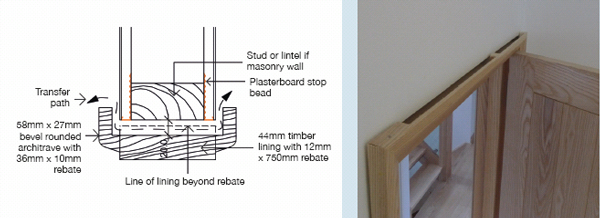
Figure 12.4 Architrave section to create hidden 20mm air transfer path, as pictured here.
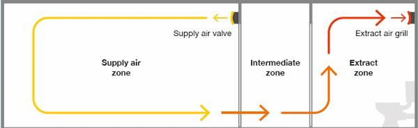
Figure 12.5 Supply, intermediate and extract zones for an MVHR system.
Incorporate the MVHR system into your scheme at an early design stage in order to ensure it works efficiently and effectively – try to minimise duct runs and bends, for example. The central unit itself can be located in a utility space, loft space, external store/garage or in a cupboard. The typical unit size for a small- to medium-sized house (60-120m² floor area) might typically be 800mm x 600mm x 400mm, plus allowance for the connections of the associated ductwork. If the manufacturer can confirm that the central unit is suitable for an external location (outside the building’s thermal envelope), rather than indoors, this can have some advantages:
• It can help to maximise the treated floor area (a services cupboard is not included in the TFA calculation in Passivhaus).
• It is more accessible if being maintained by a third party (e.g. in social housing).
• Any potential noise from the unit is outside the building (although this is very minimal).
However, an externally located MVHR unit would need suitable insulation and the condensate drain to be protected from frost, and it may not always be as efficient as an internally located unit.
The main components of an MVHR system are as follows.
• Central unit Contains the air-to-air heat exchanger and the two fans needed to push the air through the system, the two main air filters for the extract air (from the house) and fresh air (from outside). The unit should be heavily insulated, and will arrive pre-insulated if it is a Certified Passivhaus unit.
• Condensate drain Condensate is created in the heat exchanger as the extracted warm, moist air is passed by the incoming cold, fresh air: when the heat is taken out of the old warm air, it is no longer able to hold as much moisture and the water vapour it contains returns to its liquid state. The condensate drain needs be connected into the building’s drainage system and will need insulating if outside. Make sure you have access to inspect it if necessary. Apparently you can also obtain a condensate evaporator, if access to a drain is impossible.
Central unit with cover off and illustration of how cold and warm air is passing through the heat exchanger. (From top left to bottom left: Supply / Extract / Exhaust / Intake.)
• Frost protection A frost-protection strategy is needed alongside the heat recovery system, regardless of whether it is located internally or externally. This can take different forms, but the most common approach is a small electric element located on the intake duct (if the unit is indoors, as is most common, this will be between the MVHR unit and thermal envelope – see Figure 12.6 on page 200). The air entering the MVHR central unit must never drop much below zero. Ensure that the separate thermostatic sensor is located in the intake duct between the frost protection element and the MVHR unit. (A common mistake is to place the sensor between the element and the thermal envelope.) The element will preheat the fresh outside air if there is any danger of this cold air freezing the condensate that forms in the heat exchanger. If the condensate were to freeze, the airflow would be at least partly obstructed and the system would not be able to function properly. Frost protection usually kicks in at -5°C, preheating the air to just below freezing. While still essential in the mild climate of the UK, it will operate only rarely. If you have a ground source heat exchanger (GSHX), this would deliver your frost protection.
• Air filters The central unit incorporates two paper filters – an F7 (fine-particle filter) for the outside incoming air and a G4 (coarsedust filter) for extract air returning to the unit. These filter categories are common across all MVHR units. They serve to protect the unit but also ensure that the supply air is clean and your house air relatively free from dust and pollen. This is another Passivhaus comfort benefit and excellent news for hay-fever sufferers (around 20 per cent of the UK population) and asthmatics! Changing these filters is extremely simple, and you may need to renew them every three to six months, depending on your location (city or country). To check, just inspect the filter by eye – you will see when it’s dirty. Make sure you switch off the machine while changing the filters, to avoid air contaminants entering the unit. If you are in an environment with relatively clean air, two G4 filters may be perfectly adequate, rather than one F7 and one G4, which would be a cost saving; but if you are thinking of this, discuss it with your MVHR supplier first.
There is a further filter for grease, which should be located at the kitchen exhaust outlet to stop grease entering your duct system. It should be removed and washed periodically to ensure it doesn’t get so clogged that it affects the fan’s ability to pull air through it. (This could be necessary every fortnight if you do a lot of frying!) Alternatively, you can get disposable fleece-based filters. Cleaning this filter is a particularly important maintenance task (unless the unit is designed to automatically rebalance between supply and extract), as a clogged filter will reduce the rate of extraction.
In a Passivhaus you would not use a conventional extractor fan/hood over your cooker, which extracts directly to the outside. Instead you would use a recirculating hood with removable carbon or washable filters. This will also help to remove grease and smells at source. Some people choose not to use a cooker hood at all, relying on the MVHR kitchen extractor alone. Whichever your preference, we would advise against locating the MVHR kitchen extractor directly above the cooker.
There may also be a filter for the frost protector, which should be changed when the main unit filters are changed.
• Fresh air intake (or ‘ambient’) and exhaust ducts The location of these two ducts, which go direct to the outside, is an important consideration in terms of both aesthetics and performance. It is ideal if the two ducts can be oriented in the same direction, in order to avoid differential wind pressures. Do not locate the fresh air intake too near the ground; generally the air will be cleaner at height (preferably above 3m). In addition to a grille on the end, the duct should ideally be protected from rain and snow (the roof eaves can be ideal for this, or perhaps fit a purpose-made small hood). Best practice is to have a wider grille diameter than duct – use a duct reducer between the two. This will avoid any undue resistance or pressure losses in the airflow, which would then increase the power consumption of the fans. Finally, do not locate the two ducts adjacent to one another; an ideal spacing is a minimum of 2m. You don’t want to create a short circuit between the two ducts! If placed one above the other, it is better to have the exhaust above the intake, at a minimum spacing of 1m. If you decide you need an insect filter fitted, make sure it is accessible for cleaning and replacement.
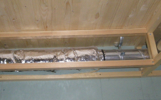
If the unit is inside the thermal envelope, then both these ducts will need to be insulated to a high standard along their full length (from the MVHR unit right up to the building’s thermal envelope), to avoid condensation on the pipe (see photo, right). If uninsulated, these pipes also become two significant thermal bridges. There is a table in the PHPP where the depth of this insulation must be entered – normally 50mm. The lengths of these ducts should be kept to a minimum, and these values must also be inserted into the PHPP. The insulation material is a non-standard product that will not deteriorate in moist conditions (technically known as ‘diffusion resistant’), e.g. Armaflex®. Make sure this type of product is what is used – it is expensive, so someone might try to skimp!
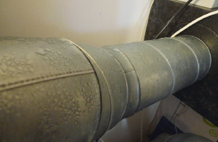
If not insulated, condensate will form on the duct surface. This picture was taken prior to insulation being installed.
If the unit is located outside the thermal envelope, then the above requirements for insulation apply to the supply and extract ducts (see below) between the unit and the thermal envelope – not the fresh air and exhaust ducts. (See Figure 12.6 below.)
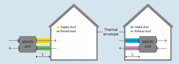
Figure 12.6 Insulation of ducts is dependent on the location of the central unit. Keep the length of these runs (L) as short as possible.
• Supply and extract ducts These ducts run from your central MVHR unit to all the rooms of your house, often in ceiling and floor voids. You can use metal or plastic ducts in a variety of shapes – round, oval or square. Pipes should be smooth internally, as this reduces airflow resistance, minimising energy use. Keep duct lengths short and runs simple – not always easy with retrofit projects. Make sure the ducts are clean before (as well as during) installation. Open ducts on a building site will be filthy! Duct runs need to be airtight: using duct systems with proprietary seals makes the process easier and more reliable than sealing each connection by hand, sometimes in awkward locations. If not airtight, ducts will become dirty and the system will be inefficient. Some systems use single-length semi-flexible ducts (running separate smooth-walled ducts to each outlet location), which eliminate this risk.
• Silencers (sound attenuators) There should be silencers located between the central unit and both the first supply and first extract terminal, or outlet (see right). You should also provide a ‘crosstalk’ silencer between adjacent rooms on a duct run (since otherwise the ducts will act as a sound transmission service!), especially where privacy is most important. An MVHR system with separate semi-flexible ducts running to each outlet/extract location will serve this purpose.
• Supply and extract air terminals Terminals are fitted in each room to either extract or supply the air. Supply outlets can be fitted with jet nozzles, which will throw the air across the ceiling (if fitted approximately 150-200mm below the ceiling, measured to the centre of the jet). These are useful if the supply outlet must be located near a transfer path or an extract zone. Otherwise, both supply and extract outlets should be positioned as far away as possible from any transfer path, to optimise airflow. Outlet valves have different shapes, depending on which way the air is flowing – if the wrong valve is installed, it will result in a streaming noise. (This is an easy mistake to make.) It’s also important to make sure the connection to the wall is airtight, so that air does not stream into construction cavities rather than the room! Avoid locating outlets near any obstructions. Outlets can be regulated to deliver or extract more or less air – normally this will be set at the commissioning stage and then fixed to avoid being easily tampered with.
• Supply and extract air terminals Terminals are fitted in each room to either extract or supply the air. Supply outlets can be fitted with jet nozzles, which will throw the air across the ceiling (if fitted approximately 150-200mm below the ceiling, measured to the centre of the jet). These are useful if the supply outlet must be located near a transfer path or an extract zone. Otherwise, both supply and extract outlets should be positioned as far away as possible from any transfer path, to optimise airflow. Outlet valves have different shapes, depending on which way the air is flowing – if the wrong valve is installed, it will result in a streaming noise. (This is an easy mistake to make.) It’s also important to make sure the connection to the wall is airtight, so that air does not stream into construction cavities rather than the room! Avoid locating outlets near any obstructions. Outlets can be regulated to deliver or extract more or less air – normally this will be set at the commissioning stage and then fixed to avoid being easily tampered with.
• Summer bypass During the warmer summer months it is useful to bypass the central unit so that incoming air is delivered direct to your rooms without heat recovery (although it is still filtered). This needs to be an automatic function to be useful. Without this feature it would only be practical to use the MVHR during the cooler months, i.e. you would need to switch it off completely in the warmer months.
Ceiling-mounted duct and silencer being ‘boxed in’, at the Camden Passivhaus.
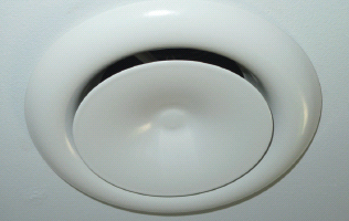
Typical ceiling-mounted air terminal. The flow rate is adjusted by rotating the central disc.
• Central control unit This should be a simple unit – generally you will need only five basic settings:
– standard setting – normal use
– reduced operation (30 per cent less), e.g. when on holiday
– increased operation (30 per cent more), e.g. when cooking or for parties!
– summer mode (bypass or switched off) – off/unoccupied mode.
If the unit is complex, then it has been demonstrated that occupants are less likely to engage with the system. Some interaction with the system is needed, however, as it is important that users feel they have some control over it. Summer mode can mean either summer bypass (see above) or that the system is switched off completely. Different users will have different preferences.
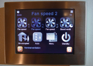
A simple user control unit.
MVHR and heating
Passivhaus reduces the space heating requirements to such a degree that a conventional heating system is not needed. There is some residual need for additional heat during the coldest winter weeks, and one of the key early design decisions relates to the strategy for providing this. (See Chapter 1, page 24, and Appendix A for a discussion of space heating options.) One approach is to deliver heat using the MVHR system, using a small radiator (called a supply duct radiator or in-line duct radiator) inserted into the supply duct just after it leaves the MVHR unit, which adds a small amount of heat into the supplied air. In a Passivhaus it should be possible to meet the residual heating need in this way. For a typical house, the size of the radiator will be approximately 300mm3.
Some MVHR units will offer an integrated heater, located within the central unit. The heat source could be the hot water store, or it could be electrical or based on a heat pump or heat main. If this is your preferred space-heating method, then the supply ducts will also require insulation – normally 20mm of a standard quilted insulation such as glass wool or sheep’s wool. There are also some suitable pre-insulated ducts on the market.
There is a possibility that the needs of heating might conflict with the air supply needs. The two requirements could be in conflict in a small room with high occupancy or a large room with low occupancy. But, given this caveat, using one system for the two purposes is an attractive solution and is fairly commonly adopted with success. Choosing to heat the air will reduce its relative humidity (RH), but this is of course true of heating generally.
If the exhaust air fan failed, cold outside air could flow right through to the heating coil and potentially freeze it. For this reason, if the fan does fail, the whole ventilation will shut down automatically.
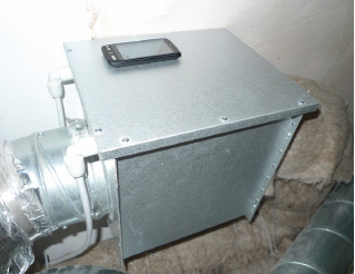
Supply duct radiator (with a mobile phone to indicate size).
The supply air temperature from the radiator must not rise above 52°C, to prevent smouldering smells from any dust in the air within the duct.
Another option is an MVHR compact unit, in which the MVHR is usually combined with air-source heat-pump technology to supply heat (through the ventilation system) as well as to generate hot water. This approach was used at both Princedale Road and Lena Gardens (Victorian terraced houses in London). The system will normally have a hot water store, which could then be connected to solar panels. Some feel that this solution is overly complex, but it does save on space – hence the name – and provides a ‘one-stop’ solution.
Efficiency of the MVHR
There is a wide variety of companies that supply MVHR units, but for Passivhaus the efficiency of the unit is critical, and many currently on the UK market would not be Passivhaus-suitable. Some units have been certified by the PHI; others might be Passivhaus-suitable, but this is one component of a Passivhaus build where the PHI strongly advises selecting a certified unit. See Chapter 7, page 106, for the criteria for a Passivhaus-certified MVHR.
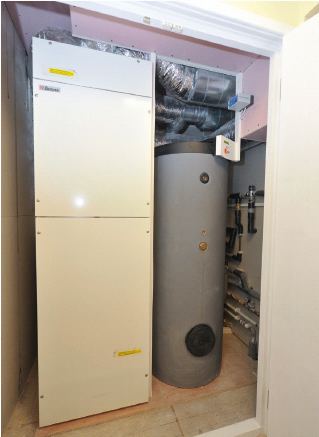
MVHR compact unit at Princedale Road, with an extra hot-water-storage cylinder adjacent.
Efficiency of the central unit
The efficiency of the heat recovery must be above 75 per cent, but there are units that can achieve over 90 per cent efficiency. Take care when offered technical information by suppliers – the efficiency measurement for a Passivhauscertified unit must be according to the testing method of the PHI and not that of other bodies or manufacturers, which are less rigorous. Along with the heat-recovery efficiency, the unit’s electrical efficiency is key. This relates to the energy used by the fans to move a given volume of air. There can be significant differences between comparable units. The PHI stipulates a maximum electrical energy use of 0.45Wh/m³ (watt hours per cubic metre [of air moved]). However, the efficiency of the whole system will be strongly affected by the layout and design of the ducting and the commissioning process. Design and installation by ill-informed parties who are unfamiliar with the technology is likely to result in poor efficiencies that are well below the unit’s capability. The efficiency as quoted assumes that:
• the whole system is balanced with ±10 per cent tolerance (supply and extract)
• all air goes through the exchanger and none is lost through leakage in the unit
• ducting layout is as per the design (as short as possible and sized correctly)
• airtightness in the building is as per the design intent
• there are no undue heat losses in the ducting due to poor installation/insulation.
MVHR efficiency and airtightness
All other factors being equal, an MVHR system will perform more efficiently the better the airtightness of the building. For an MVHR to be an efficient and appropriate choice, i.e. to improve energy consumption, it must be combined with a high standard of leak-free design. The general rule of thumb is that an MVHR should only be installed in buildings achieving an airtightness of 3ach at 50Pa or better. One recommendation3 is that a maximum rate of 1.5ach at 50Pa should be the target to ensure efficient performance. This is also the statutory standard in Germany. Since the Passivhaus standard is 0.6ach at 50Pa, we would strongly advise that low-energy designers aim to achieve this target if MVHR is to be part of their selected ventilation strategy.
In a development of Passivhaus apartments in Hanover, Germany, it was calculated that for every 1kWh of electricity used by the MHVR unit, 16.5kWh of heat was being conserved through heat recovery. Even if you take into account the inefficiencies in electricity generation (primary energy), this still represents a very impressive ‘coefficient of performance’ (COP). A correctly installed unit in a typical house might use around 1kWh of electricity per day (equivalent to around 15p a day at current prices). If saving more than 16.5kWh of natural gas, for example, and assuming a gas price of 5p per kWh, clearly there would be a big net saving.
Obviously this efficiency does not apply if using an MVHR in ‘summer bypass’ mode, but a thrifty occupant can always choose to switch it off outside the cooler months and open their windows instead!
Efficiency and commissioning
The commissioning process for an MVHR system is very important and requires skill and knowledge. Make sure you use someone with a certain amount of experience to design the layout of the system and specify the components, as well as commission prior to handover. Generally, MVHR units have required a thorough balancing of the system at the commissioning stage, but some newer systems have self-balancing mechanisms, which simplify this process and ensure that ongoing balancing is maintained. Manual balancing will take some time – if experienced, perhaps half to one day – to ensure that everything is operating according to the design plan. If the system is not adjusted initially, it will not operate as you expect! Needless to say, the advantages of a whole-house mechanical ventilation system, such as conferring a more comfortable indoor climate, are only achieved if the system is designed, installed and commissioned to work as intended.
Part of the commissioning will be to ensure that the supply and extract air fans are properly balanced and that noise levels are within allowable limits. For this the intake and exhaust airflows will also need to be measured, as well as the wind velocity on the day of commissioning. On windy days, it cannot be accurately commissioned.
Each air inlet or outlet needs to be adjusted so that it is either extracting or supplying the amount of air intended (the maximum deviation is 10 per cent). The air valves in most systems will need adjusting several times, as changing one outlet affects all the others. Once complete, the outlet and inlet valves should be fixed using a locknut or similar so they cannot be tampered with. Using a ‘flow-finder’ device is generally accepted to be more accurate than other measurement methods, and is recommended by the PHI. This is based on zero pressure compensation, i.e. the airflow is hardly affected by placing the device in front of the outlet. A vane anemometer, on the other hand, works by being placed over the duct; the airflow stream then hits the vane, making it rotate. Some conversion of the reading may be necessary, depending on the units of measure the anemometer supports.
The PHI is encouraging the development of self-balancing systems, as these will avoid much of the complexity of commissioning described here.
Sound considerations
The PHI sets a maximum noise level of 25dB(A) (‘A-weighted’ decibels) in living spaces, so the system should effectively be silent at supply locations. At extract locations it should be virtually silent, at 30dB(A). The permitted noise level at the unit itself is slightly higher: 35dB(A) (still very low, but audible). Meeting these standards does require design input – it won’t just happen.
Sources of sound could arise from ‘crosstalk’ between rooms (the sound being transmitted via the ducts) or from the unit fans or other structure-borne sound causing the ducts to vibrate. All of these can be designed out. Being aware of them should help anyone buying or specifying such a system to check that the installation has included the following:
• The supply ducts are isolated or ‘decoupled’ from the unit with a semi-flexible PVC pipe connector (not aluminium).
• A crosstalk silencer is fitted between every connected room, and between the unit and first supply and first extract outlet (this also helps with decoupling the supply ducts from the unit). Note that on some systems you would connect separate supply semi-flexible ducts from each extract and supply point back to a central acoustically lined plenum box, and therefore would not need silencers between rooms.
• The duct runs are kept as short and simple as possible (not always easy with retrofitting), which reduces the likelihood of vibration in the duct. This means minimising bends.
Some MVHR suppliers have told us that silencers are not needed, but we would not be content to install a system without such provision.
Fire considerations
If ductwork must cross through a fire compartment (e.g. between adjacent flats), then there are fire shutters available as well as cold smoke shutters, but in a single-family dwelling this should not be needed.
Objections to mechanical ventilation (MVHR)
In a conventional building, we already use mechanical energy in our ventilation strategies when we extract air from our bathrooms and kitchens. Using energy to draw fresh air into our homes, however, causes concern for some.
The energy use for the fans is regarded as wasteful in a low-energy building when a natural solution could be adopted. This argument is flawed, since, as we have seen, the energy saved by using such heat recovery systems far outstrips the small power required by the fans. Not only can heat be recovered from the exhaust air, but with mechanical ventilation the building itself can be constructed to be less leaky.
A further objection might be the energy used in manufacturing such a system. The ventilation system, as noted already, is integral to the overall low-energy strategy, which includes negating the need for a conventional heating system. Also, by reducing the overall energy requirements, any renewables (photovoltaic panels for electric energy and solar-heated water) used to achieve zero carbon can be kept to a minimum. In this way the energy invested in the system is more than compensated for by savings elsewhere.
Another, perhaps significant, anxiety is what happens if the system fails. The unit is a relatively simple piece of kit. If it did cease to operate, there would be no immediate repercussions, and windows can always be opened. Air is entering and leaving the building all the time (doors and windows opening and shutting, etc.). In summer the whole system can be turned off, in any case! A building is not a hermetically sealed bag, even with low air leakage levels. In winter, if the system did fail, you would eventually notice increased stuffiness and smells. The dangers relating to a faulty gas boiler are potentially far more serious, and most of us manage to have these in our homes without undue concern. MVHR units have been used widely on the Continent for many years.
Poor design / construction skills
Sadly, in the UK there are many accounts of MVHR systems being poorly installed. Common mistakes are:
• missing insulation on fresh air intake or exhaust ducts
• missing filters (especially the grease filter on kitchen exhaust)
• air intake adjacent to a pollutant source (e.g. compost heap or dustbin cupboard)
• poorly installed ducts (e.g. lots of twists and turns; ducts not clean when installed; not airtight)
• supply and exhaust airflows not balanced at commissioning (making the system inefficient)
• condensate drain poorly installed (no trap or an inadequate fall)
• supply and exhaust ductwork connected the wrong way round (or wrong outlet type fitted).
These are not complex problems and stem from general unfamiliarity with installing such systems. On smaller projects it is much easier to manage this type of quality issue; however, on larger commercial projects the risk of errors increases. If you are building in a culture where the levels of workmanship associated with achieving the Passivhaus airtightness standard are far from normal (certainly in the UK), or where MVHR is a relatively new concept, then there is a real risk of seeing badly installed and poorly performing systems, and this is likely to continue to be the case in the medium term. This will be exacerbated if training does not form part of the drive to achieve good-quality low-energy housing. As discussed in Chapter 4, in the UK we are extremely poor at providing contractor training. The government is moving swiftly towards legislating a zero carbon standard (due for implementation in 2016) without ensuring integrated training. As we will almost certainly see the increasing use of MVHR systems (perhaps becoming the dominant form of ventilation post-2016), training in specification and installation of these systems is something that needs to be addressed at national policy level.
As noted, the correct commissioning of the MVHR unit is crucial, and it would be sensible for the client / architect / Passivhaus Designer/Consultant to attend this. The advice in this chapter should help to ensure the basic mistakes outlined above are avoided!
Briefing the user
Part of ensuring a successful installation involves communicating with the occupant(s) so that they understand the basic principles and are clear about the requirement to change and/or clean filters. Modern units will alert you when to make filter changes. Everyone needs to understand what the ventilation outlets are, and that it is important they are not tampered with or blocked.
MVHR units should come with user guides, but far more important is that the user controls are intuitive, and at present this is not always the case. Given the simple nature of an MVHR unit, straightforward user controls should be achievable for manufacturers.
MVHR and the future
It needs to be appreciated that these systems are being continually improved and refined. It is likely that future units will be designed for a more straightforward commissioning process and it is hoped that certain components (particularly the frost protector and supply heater) might be integrated into the central MVHR unit – this appears to be the current trend.
RECAP
The use of mechanical ventilation with heat recovery (MVHR) is an essential part of the Passivhaus mixed-mode ventilation approach, and the PHI strongly recommends that the MVHR unit is Passivhaus-certified. There is no other viable ventilation solution at the low air leakage levels needed in an ultra-lowenergy house.
The system is straightforward, but does require early design consideration and needs to be installed and commissioned properly. This is no more complex than correctly installing a gas boiler, but in the UK we do not yet have the equivalent wide knowledge base and experience.
With growing concerns about air quality and health, ensuring good indoor air quality (IAQ) is critical. Available research already indicates that a correctly installed and operating MVHR has a positive effect on IAQ and humidity levels. Passivhaus uses the European air quality level IDA 2 (CO2 levels of 400-600ppm) to inform its MVHR operating parameters.
MVHR is essential only in the winter months, while in the warmer season you are likely to naturally ventilate your home by opening windows. It is usually possible to provide your residual space heating requirements through the ventilation system, using a supply duct radiator.