CHAPTER NINE
Airtightness and sequencing
Air leakage and Passivhaus, internal air quality (IAQ), airtightness standards, wind-tightness, breathable materials, airtight materials, air leakage at the design stage and construction stage, sequencing, on-site communication and training, airtightness testing, typical airtight construction details
Perhaps the most debated aspect of the Passivhaus standard is its commitment to extremely low air leakage rates. This causes real concern for some people, particularly regarding issues of air supply. This chapter looks at the requirement and explains why this is adopted and how air quality and air supply are addressed. It reviews the important subject of the airtightness standards being proposed for the UK zero carbon standard (see also Chapter 5) and how these relate to Passivhaus. It looks at the practical challenges of achieving low leakage rates, and at typical Passivhaus construction details and how these can affect normal work sequencing.
Air leakage and Passivhaus
The Passivhaus standard stipulates exceptionally low air leakage levels, commonly referred to as airtightness. This is defined as the unplanned movement of air through the building’s thermal envelope (walls, floor and roof, including any party walls). To meet the standard of below 0.6ach (air changes per hour) at 50Pa (pascals – the unit of force per unit area) above and below ambient atmospheric pressure, you are aiming to achieve leakage paths equivalent to less than the area of a 5p coin over every 5m2 of envelope area. The main benefits of reducing air leakage are:
• saving of heat energy lost along with the escaping air
• improved performance of the insulation
• better comfort levels
• durability of the building fabric (minimising vapour moisture entering the fabric).
In a typical standard-build house, 15 per cent of heat loss can be attributed to escaping air, but it is in the improved performance of the insulation that the greatest energy benefit lies. Studies have indicated that even with the smallest of air leakages into the insulation layer (via gaps in the airtight layer of only 1mm wide), the insulation’s thermal performance is significantly reduced (in one experiment, for example, performance altered from a U-value of 0.3W/m²K to a U-value of 1.44W/m²K – a factor of nearly five).1 This is something that has not been properly appreciated by the building community and lies at the heart of the success of Passivhaus in delivering low energy performance, not just design intent. The failure of our low-energy buildings to perform as designed is widely recognised in the UK, and this failure is linked to a fundamental misunderstanding – simply installing insulation is not sufficient to guarantee performance. It must not be forgotten, however, that the third reason for reducing air leakage is simply comfort, i.e. the elimination of draughts and cold surfaces.
Achieving low air leakage levels has been demonstrated to be possible with all types of construction, from lightweight (timber) to massive (masonry). Success depends on ensuring continuity of the airtightness layer and on careful workmanship. Some would argue that wet constructions (masonry/concrete) are easier to make leak-free, as the airtightness solutions will be more tolerant of poorer workmanship – a concrete box perhaps being the easiest solution. However, choice of construction method and materials is influenced by a wide range of factors, and the Passivhaus standard deliberately does not favour one construction type over another.
Airtightness and indoor air quality (IAQ)
There is a degree of natural scepticism about achieving good indoor air quality (IAQ) while also achieving ‘airtight construction’. A general anxiety remains that occupants might be left gasping for air! It would therefore be more helpful to describe such construction as ‘leakfree’, since most of us can understand the discomfort of a draughty room, especially on a cold day. In a cold and draughty house, we are inclined to avoid sitting next to windows and instead will gather around an open fire to enjoy the radiant heat. The high air change rates experienced in our typical buildings (an average air permeability of 7m³/hr/m² at 50Pa for UK new housing) might exceed what is necessary for our fresh air needs, but the disadvantages of such high rates are accepted as normal and tend not to be consciously acknowledged or considered unavoidable. For many, it is likely that only the experience of a true Passivhaus building will allay their nervousness about what is an unfamiliar approach. In a Passivhaus, fresh air is introduced by a simple mechanical method (see Chapter 12) and applied to the whole building in an integrated and controlled manner, ensuring that good air quality can be maintained throughout while avoiding oversupply (draughty) or undersupply (stuffy or smelly conditions). In contrast, using uncontrolled infiltration of air, such as trickle vents in windows, means that ventilation levels in the house rise and fall as wind speeds and temperature differences fluctuate, and that some spaces may be oversupplied while others remain undersupplied.
A key concern when deciding on a low-energy ventilation strategy is to ensure that potential pollutants in the indoor air are kept to a minimum. There have been very few academic studies on air quality in the home, but there is a growing body of concern about the possible link between the increased use of chemicals (glues/ adhesives, sealants, varnishes, paints, carpets, fabric treatments, insulations, etc.) and an increase in the incidence of respiratory and skin disorders. Our older houses had no planned ventilation strategies; there were no window trickle vents or mechanical bathroom extraction systems – the air was purged and replenished simply through the general leakiness of the fabric. This was good for the level of most pollutants, but bad for energy consumption – assuming you want to live at a minimum of 20°C – and not great for comfort levels either. More energy-efficient (less leaky) buildings are necessarily reliant on planned ventilation strategies to maintain IAQ. In Chapter 12 (page 192) we refer to a study that demonstrated that much lower carbon dioxide levels were recorded in a Passivhaus apartment block with mechanical ventilation than in an older apartment block that relied on natural ventilation. (Carbon dioxide is an accepted marker for the wider mix of potential indoor air pollutants.)
Volatile organic compounds (VOCs)
Volatile organic compounds (VOCs) are chemicals that become a gas (evaporate) when at room temperature; a process referred to as ‘off-gassing’. Commonly used building materials off-gas and thereby introduce contaminants into the indoor air. Extensive measurements have shown that the air in a typical home contains a large range of these VOCs. Most off-gassing happens at the early stages of exposure of the materials to room temperature, so leaving windows and doors open for a period before occupancy will help to significantly reduce such contaminants. Perhaps two to four weeks’ 100-per-cent fresh-air flush should be incorporated into build programmes, especially if using ‘off-gassing’ products. However, products can continue to off-gas for years after installation, albeit at a lower level. We would therefore advise sourcing low-emitting or non-emitting products for an ultra-low-energy build – look for words like ‘solvent-free’, ‘waterbased’, ‘low-VOC’ or ‘non-toxic’. Products buried within walls, i.e. not exposed to air, are less of a concern, but surface finishes should be carefully considered. The fitting and using of any such materials can be very unpleasant for installers, and it is clear from having quizzed workers on-site that the matter should be a serious consideration. Paint products are already being improved as a result of EU legislation, so the concerns highlighted here are now being officially acknowledged. These issues are of, course, part of what drives people to adopt a philosophy of using only ‘natural’ building materials, as discussed in Chapter 5.
Airtightness standards
The measurement of air leakage is done using pressurisation tests during the construction period. This involves both pressurising and depressurising the interior of the building using large fans, normally attached to a door or window opening (more details on page 137).
While the test and kit used is common to Europe, the USA and the UK, the units of measurement vary and can cause confusion when making comparisons across projects or standards. The Passivhaus airtightness requirement of 0.6ach is measured at 50Pa, so the airtightness test applies a pressure of 50Pa above and below ambient atmospheric pressure against the interior of the walls of the house. This pressure is equivalent to a depth of 5mm of water applied over the surface of the building, and the air changes per hour at this pressure is often referred to as the n50 value. This refers to the flow rate of air entering and exiting the building (in m3/hr – cubic metres per hour) divided by the ventilation volume, Vn50 (the total internal air volume, in m3).
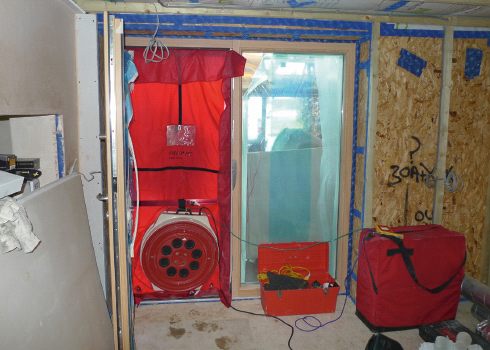
Site blower test. A large fan, attached to the door frame, is connected to specialist software used to calculate air permeability and air change rate.
This n50 value is different from the figure currently used in the Standard Assessment Procedure (SAP) calculations in the UK. SAP calculations are required to meet the UK Building Regulations (Part L1A for new dwellings) in England and Wales. The SAP figure is usually referred to as the q50 value and is measured in m³/hr/m², also at 50Pa above and below ambient atmospheric pressure. This refers to the cubic metres volume of air entering and exiting per hour per square metre of thermal envelope area (walls, roof and floor and including party walls if semi-detached or terrace), and is what is described as the air permeability of the building. The area of the internal surfaces excludes the surfaces within window and door reveals, and, while for this reason it is generally agreed not to reflect accurately the real air infiltration rates, it does allow useful comparison between projects.
The Air Tightness Testing and Measurement Association (ATTMA) is the main professional body whose members are qualified to carry out airtightness testing in the UK. They will measure the q50 value. To change the q50 value to an n50 value for Passivhaus, you need to multiply q50 by the thermal envelope area (measured as noted above) and then divide this by the internal air volume of the house. It is often quoted that 1m³/hr/m² at 50Pa equates to approximately 1ach, but this rule of thumb strictly applies only to a particular volume, equivalent to 6m x 6m x 6m, and therefore should not be universally applied. For other building volumes, discrepancies between measurements of air permeability (q50) and ach (n50) can be significant. Remember that the q50 value is a function of the enclosing surface area, while n50 is a function of volume. Often the surface area and volume are similar numerically, but not always!
Note that to obtain a value for air changes per hour under normal conditions (typically 4Pa air pressure difference), i.e. not at the test pressure of 50Pa, a useful guide is to divide the n50 value by 20. If the site is particularly sheltered, it is often advised that it would be more accurate to divide the n50 value by 30, and if the site is very exposed, by 10.
Current typical air permeability for new houses in the UK is 7m³/hr/m², while current (2010) UK Building Regulations (England and Wales) are set at 10m³/hr/m², so we can see that the step change required for the Passivhaus standard is quite significant. With an air permeability of 7m³/hr/m² we are throwing away significant heated volumes of air!
Airtightness standards compared
It is interesting to compare standards for airtightness internationally as well as within the UK – see Table 9.1 opposite, which shows a selection of statutory and voluntary standards. The highest statutory standard is in Sweden, and it is in these colder European countries that the value of airtightness has been recognised for some time, mainly for improved comfort levels. Countries with milder climates have, until recently, shown little, if any, interest in achieving airtight construction. The new motivation for more stringent statutory standards is less to do with comfort and more to do with energy use, but the comfort benefits are already well appreciated.
The question of why Passivhaus sets the airtightness target at a maximum of 0.6ach is of interest. Both the current UK zero carbon standard and the UK Energy Saving Trust best practice advise an air permeability (q50) of 3m³/hr/m² – an air leakage limit where non-mechanical ventilation solutions can still be applied. Below this figure it is considered necessary to introduce planned ventilation solutions, typically involving a form of whole-house ventilation with heat recovery. By setting future regulations at 3m³/hr/m², building solutions using only natural ventilation techniques remain viable (normally some form of ‘passive stack ventilation’, driven by natural vertical pressure differences). These natural techniques will generally use standard window trickle vents to draw in fresh outside air. This approach carries with it an energy penalty, as a result of both higher leakage rates and the absence of heat recovery technology. We look in more detail at heat recovery ventilation in Chapter 12, but at this point it is sufficient to note that an efficient heat recovery system, properly designed and installed, can recover more than 90 per cent of the heat energy from the exhaust air.
Table 9.1 International airtightness standards
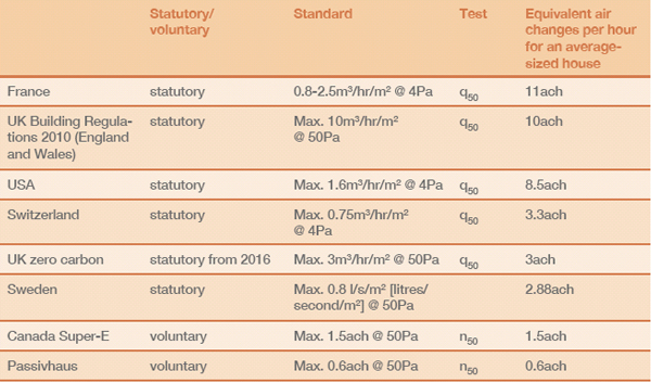
Adapted from Limb (2001)2
It is notable that the UK’s zero carbon standard for new homes, currently still under review, includes a space heating target of 39-46 kWh/m².a compared with the Passivhaus standard of 15kWh/m².a. Given the target leakage rates of 0.6ach for Passivhaus and (currently) 3m³/hr/m² for UK zero carbon, the direct link between target leakage rates and energy in use is clear. It is also worth remembering that the method for measuring the treated floor area (TFA) is not the same in the PHPP and SAP, which is the current basis for the zero carbon targets, so the square-metre floor areas used in the space-heating targets are not directly comparable. SAP has more favourable rules for measuring a building’s floor area (see Chapter 7, page 94), which means that the zero carbon 39-46kWh/m².a is actually equivalent to over 50kWh/m².a in Passivhaus terms.
The adoption of this lower airtightness standard in the UK in part reflects a cultural unease, as noted at the beginning of this chapter, with the concept of introducing fresh air into our homes by mechanical means, i.e. fans. However, most of us are experienced in managing what is known as ‘mixed-mode’ ventilation without perhaps realising it – in our cars. We open the car windows on bright, sunny days and enjoy the fresh outside air, while on other days (in heavy traffic, or in colder, wetter weather) we close the windows and rely on the clean, filtered, mechanically introduced air. In reality, mechanical ventilation systems are simple, relying on few working parts and offering many benefits in terms of internal air quality.
Whole-house mechanical ventilation is integral to the Passivhaus approach (see Chapter 12), and the airtightness standard needs to be below 1.5ach at 50Pa for this to be an efficient solution, i.e. generally recovering more energy than the Passivhaus-certified MVHR unit uses. The 0.6ach at 50Pa target allows for some loss of airtightness over the lifetime of the building without any undue effect on overall performance (e.g. on MVHR performance). The target also ensures there are no draughts with a velocity of more than 0.1m/s (metres per second), which is the speed above which we would physically begin to notice them. The effect of this non-draughty environment is argued to result in occupants setting thermostats to a lower air temperature (by as much as 2 degrees), since they feel warmer. This is a further example of Passivhaus functioning as a comfort standard as well as an energy standard.
Wind-tightness and thermal bypass
Passivhaus differentiates between airtightness and wind-tightness. Normally there is a designated wind-tight layer on the external side of the construction, coupled with the airtightness layer on the inside of the construction. The wind-tight layer acts like a protective wind-cheater, which improves the thermal performance of your woolly jumper by keeping air out. Reducing ‘wind-washing’, i.e. the penetration of air into and around the insulating fabric from the outside, improves the performance of the insulation. A good example is external insulation applied to a masonry substrate. Traditionally the fixing might have been carried out using ‘dabs’ of glue, but for Passivhaus a continuous layer of glue is required. The movement of air in and/or through an insulation layer is referred to as ‘thermal bypass’ (see Chapter 8, page 112). The air may travel through the fabric and return to the outside without affecting airtightness as such; the detrimental effect is in the lowered performance of the insulation itself. Insulation is not fully effective unless it is installed without gaps, voids or compression, and is aligned with a continuous air barrier (any durable material that restricts airflow).
Breathable versus airtight
A common misconception arises from the difference between the ‘breathability’ of construction materials, i.e. their ability to allow water vapour through them, and the airtightness of the construction. It is equally possible to build to the Passivhaus airtightness standard using either materials that are vapour permeable (‘vapour-open’) or those that function as vapour barriers (‘vapour-closed’ materials). This is because a material can be impervious to mass air flow – the movement of the body of air as a whole – but can still allow gases (vapour) to move by diffusion (‘percolate’) through it. This diffusion is driven by the difference in the pressure of vapour – the vapour pressure differential or gradient – on each side of the membrane. In an occupied building, there will be a higher concentration (higher vapour pressure) of water vapour on the inside, so the vapour pressure gradient will encourage water vapour movement from inside to outside. ‘Vapour permeable’ or ‘vapour-open’, then, in a construction context, is usually taken to mean ‘permeable to water vapour’.
Materials also vary considerably in how vapour-open’ they are: we usually refer to this characteristic in terms of vapour permeability levels. Some helpful illustrations are given in the next chapter. The different units used to measure vapour permeability can cause confusion, so ensure that like-for-like measurements are being used if you are making comparisons between products. A good example of an airtight but ‘breathable’ or ‘breather’ material is Gore-Tex®, commonly used for walking and climbing clothes – this keeps the wind (air) out while continuing to allow moisture vapour from your body to escape to the outside.
An example of a vapour-closed or impermeable material is a rubber membrane (perhaps functioning as the watertight layer under a living roof). One example of a vapour-open material often used in buildings is woodfibre board, which might be included towards the outside of a timber-frame wall, where transfer of moisture to the outside is important. When using natural materials, such as timber, careful management of moisture levels within the construction is essential to ensure that materials can dry out if necessary. Water could be present due to a temporary accidental ingress (it does happen!), or materials could have become wet during the construction period and subsequently need to dry out. Traditional constructions have generally allowed moisture to be present, but also ensured that drying out occurred. Cyclical wetting and drying need not have detrimental impact, for example, in the case of rubble/stone solid walls. It is the trapping of moisture within constructions that can have the most catastrophic consequences. It is good practice to encourage moisture to move from the inside to the outside of the construction by using successively more vapour-permeable materials. As a useful rule of thumb, the vapour permeability of the material on the outside should be five times more than that of the material on the inside.
Intelligent breather membranes
The latest innovations in permeable materials are ‘intelligent’ membranes. These breathable sheet materials have varying vapour permeability characteristics, depending on the relative humidity (RH) levels on each side of the membrane. This means that the membrane will be more vapour-open during the summer months, for example, when the average humidity level at the membrane is high – so if there is moisture trapped within the assembly, this can allow some drying out to the inside of the construction. Alternatively, if the average humidity level at the membrane is low (e.g. during winter months), the vapour permeability of the membrane decreases, protecting the fabric from moisture/ vapour penetration into the construction and reducing the risk of interstitial condensation (condensation that occurs within a building assembly – see Chapter 10, page 147).
Intelligent breather membranes can be used as the airtightness layer for both wall and roof constructions. If used as the airtight layer within a timber assembly, they should be stapled frequently (say, every 100mm). The overlapped joints between sheets are then taped with an appropriate airtight tape. If counter-battening over the membrane (say, to form a service void), fix the counter battens over the top of any taped joints for a very robust solution.
Airtight materials
As noted, the airtightness layer is normally located towards the inside of the construction; this is often within a service void, for protection. The airtightness layer stops unwanted air leakage from the interior to the exterior, as well as helping to limit airborne moisture from the interior migrating into the structure, with the potential to cause deterioration to materials and decreased thermal performance. Moisture within the fabric of a building is the single most common cause of material degradation and building failure. Most insulation products are poor at stopping airflow. An effective air barrier is contiguous (continuous) across the entire building envelope, with all holes and cracks fully sealed, and should be in full contact with the insulation (referred to as ‘fully aligned’).
The most commonly used airtight materials are gypsum plaster or oriented strand board (OSB) of sufficient quality and thickness. Metals such as steel beams are (obviously) airtight, as is most concrete, as long as it is of a suitable quality. Ground-floor concrete slabs are therefore commonly used as part of the airtight layer, but this will need to be monitored for quality. Various membranes or sheet materials are also airtight, such as EPDM (ethylene propylene diene monomer) rubber-based sheets, polythene, polyethylene and ‘intelligent’ membranes. Table 9.2 below lists the relative airtightness of different materials.
Addressing the junctions between construction elements – such as where windows meet walls, and walls meet roofs, etc. – is key to achieving airtightness. These places are often where the airtight layer changes from one material to another, and most commonly such transitions are handled using a variety of airtightness tapes. The lifespan of these tapes is sometimes a cause for concern, and is yet to be 100-per-cent demonstrated, as buildings using such tapes are all relatively recent. The first Passivhaus, built in 1991, is still performing as intended, demonstrating a tape life of at least 20 years. There are manufacturers of such tapes who guarantee a minimum life of 60 years – and airtightness products have obtained Agrément Certificates (see box opposite), part of which would involve accelerated ageing tests. There is at least one Irish Agrément Certificate that covers an airtightness system including tapes and which concludes that the airtight system will have a life comparable with the other elements of the construction.
Table 9.2 Materials that are suitable/unsuitable for airtightness layer
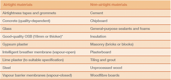
* But see box opposite
This is an approval system awarded to a product after it has successfully passed a comprehensive assessment involving laboratory testing and which includes continued monitoring of the product after the certificate is granted. Various countries, including Britain, Ireland, France and Germany, run these product-approval systems.
It is best practice to protect these tapes with a covering layer to avoid future damage. Often tapes are part-buried within the plaster layer, which will further ensure longevity. Similar glues to those used in airtightness tapes are employed in other industries in far more aggressive and demanding environments, so there is good reason to trust that the tapes will perform in the long term. Should the airtightness deteriorate a little over time, a Passivhaus should still continue to operate as designed, and certainly better than required by the current zero carbon standard, although there would be some small energy penalty. The mechanical ventilation would continue to operate effectively at up to 1.5ach.
Airtight tapes are not always easy to stick into place, and if this is found to be a problem it will normally be related to dust (use a primer first) or moisture levels. If the surface of a membrane is damp, for example, adhesion will be problematic and the surface will need to be dried first (a hairdryer can be useful!). If possible, avoid using the tapes while the atmosphere is damp.
Neither brick nor block walls are airtight, and typical mortar joints will often prove to be very leaky. The tendency for long-term deterioration of mortar joints (eventually requiring repointing) means that careful consideration is required if intending to retrofit older masonry buildings to any level of airtightness. For wind-tightness, repointing of the external mortar joints is likely to be necessary if insulation is to be applied internally. This is to avoid both thermal bypass and rain penetration (especially if on an exposed site). Traditionally, the surface area of wall located within the internal floor zone (above the ceiling and below the floorboards) was never plastered, so this will be another particularly ‘leaky’ area. With Passivhaus, the plastering of these previously hidden areas is a significant change from traditional building practice.
OSB airtightness
Oriented strand board (OSB) is made airtight by taping along the joints between adjacent boards using airtightness tape. The normal recommendation is that OSB should be a minimum of 18mm thick. However, it has been discovered that some boards at this thickness are not airtight – this probably reflects some variation in board composition as supplied by different manufacturers. A simple blower test prior to use (use a balloon taped against the board surface and blow air against the opposing side) will confirm whether the board is up to the task. In some projects the boards have had to be lined with an airtight membrane after the problem was identified post-installation. A better recommendation might be to use OSB/3 grade boards and maybe at 22mm thickness. For those who are interested, there is a useful study on the air permeability of eight different brands of OSB.3 The study reveals a wide range of permeability, even within same brand boards, and suggests a shift to using a recycled-wood-based panel instead of the OSB, with an additional airtight top layer (e.g. a membrane or foil).
It is important to ensure that inappropriate materials are not used onsite instead of more expensive and specific airtight tapes and glues; in particular, polyurethane foam or silicone sealants are not acceptable and will not be durable over time.
Avoiding air leakage at the design stage
Identifying the airtightness layer early on in the design stage is critical, as the construction methods and materials to be used will affect which airtight materials are appropriate. Key drawings highlighting the airtight layer (often blue or red are used as a colour code) should be prepared – normally by the architect – for use by the construction team. An example is shown in Figure 9.1 below.
The airtightness layer should be continuous and run around all the building elements (floor to wall; wall to roof, etc.). Each transition point, usually at construction junctions, will need to be detailed separately (as in Figure 9.1) so that the site team is clear about how the airtight layer transitions from one material to another, or wraps around elements such as intermediary floors. This process will soon highlight the fact that there is a need for particular sequencing of the work in order to achieve this continuity. It is therefore helpful if any unconventional sequencing can be highlighted on the construction drawing, as in Figure 9.2, page 135. And, although a wide range of tapes is available, each for a specific situation, it is often simpler to limit the number of tape varieties specified to avoid the potential of misapplication on-site.
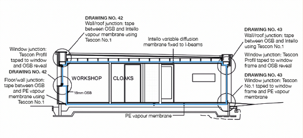
Figure 9.1 Key airtightness drawing.
Be practical about the location of sockets, using internal rather than external wall positions if there is a choice (in a retrofit, avoid the first 1.2m from external walls). The need for service penetrations through the external envelope should be kept to a minimum. Often a 50mm service void is created on the inside of the airtightness layer. Simplifying the junction details and avoiding too many different transitions between airtight materials will also help.
During construction, the need for power cables to run a variety of tools creates a risk of additional, unplanned holes through the fabric. It is also true that future services might require penetrations through the fabric after the building is complete. It is therefore suggested that at least one spare entry point is designed in, and noted on the drawings. A single grommet with multiple entry points could be used.
If formally tendering to contractors who have no experience of building to high airtightness standards, it would be wise to meet face-to-face with any of those being considered and to specifically discuss the airtightness issues with them. Decide how realistic they seem to be about the challenge being set them, and how well informed they are. The airtightness standard is a challenge for the construction team, and no amount of design detailing will solve poor attention to detail on-site – even if it is carefully hidden from the eye! Ensure that the expectations and targets are clearly documented within the tender, including the provision of the airtightness tests and the requirements for on-site training or induction sessions relating to airtightness. Passivhaus Certification also requires photographic records to be made during construction. Make sure that this is clear to the contractor and that how it is to be managed is also quite clear. Taking good photographs will provide useful information for future training, in any case. Ensuring the right choice of construction team is discussed in more detail in Chapter 6.
Avoiding air leakage at the construction stage
The process of achieving an airtight building will soon highlight the need for close cooperation between the different trades. The need for a well-managed and integrated workforce cannot be overemphasised; careful workmanship and tight supervision are the key requirements.
The commonplace tendency not to provide on-site workers with a broad-based briefing (the ‘how and why’) of the project in hand contributes to a build process that becomes a series of isolated interventions by workers aware only of their own tasks and not of the potential wider implications of their work or habits. This will cause havoc for those wanting to achieve an airtight construction, and part of the remedy is to ensure that proper induction sessions are held.
At the construction phase (on-site work), we would advise the inclusion of an initial induction session for the whole workforce. This can be useful to explain the overall approach of Passivhaus for those unfamiliar with it, as well as to run through the essentials relating to airtight construction. It is critical to ensure that key drawings (e.g. airtightness diagrams – see Figure 9.1 opposite) are always available for inspection on-site and that there is a clear understanding of which materials constitute the airtightness layer on each element of the building’s envelope (wall, floor, roof, etc.). The tendency for different trades to follow each other in sequence (electrics, plastering, decorating, etc.) and to subcontract their work allows for ‘grey’ areas of responsibility to arise, and for blame to be shifted from one party to another. The key, then, is to find a way to help each group understand the final goal and the reasons for it, as well as help them appreciate that each has a significant contribution to make. It is important that the consequences of not delivering a contiguous airtightness layer are understood, including serious material degradation through moisture ingress (see Chapter 10). Poor practices such as the ‘build–damage–install– repair’ cycle, which occur too commonly on UK building sites, will prove enormously problematic if trying to achieve such demanding airtight levels. Hidden areas (under stairs, in floor voids, under baths, etc.), which are commonly very poorly finished, must be finished as effectively as other areas, and this must be communicated at the outset.
It is advised that an on-site ‘airtightness champion’ is appointed (this need not be that person’s only role!), although no single person can guarantee that all mistakes are picked up – work can be swiftly concealed in the natural process of building. Therefore it is important to encourage the entire team to have a responsible attitude towards airtightness. Meeting the Passivhaus standard of 0.6ach need not be onerous if a whole-team approach can be achieved. Making walls, floors and junctions airtight is not, in reality, overly complex or difficult to learn. An informed workforce can easily be encouraged to think in airtightness terms and may soon be suggesting improved techniques and solutions. Any problems or proposals need to be reported to the airtightness champion so that proper feedback and ongoing learning is in place.
There are additional costs associated with achieving a continuous airtightness layer, in particular budgeting for extra internal plastering, where it is being used as the airtight layer. In retrofit projects, it would be wise to include the complete removal of the existing plaster in the budget, as a contingency, unless it is certain that it is completely sound. Some of the proprietary products available (e.g. airtight back boxes for electric sockets and grommets for cables that penetrate the airtightness layer) are not always essential, and on-site solutions can be perfectly effective (e.g. setting the electric socket into wet plaster when being fitted). Care must be taken with flat-profiled cables when using grommets with round holes – the grommet may not then secure an airtight finish.
The most common areas of weakness are door thresholds and the junctions between windows and reveals, so it is worthwhile paying additional attention to the workmanship in these areas. In particular, windows are often installed by a window subcontractor, who may not be used to fitting the expensive, high-performance Passivhaus windows essential to such a project. The thermal performance of these windows is very much affected by how efficiently they are installed in the window opening (see Chapter 11). UK installers are very unlikely to be familiar yet with the accuracy and care required and we would advise caution, even if using approved installers. The sequencing of and responsibility for window installation needs careful thought (see ‘Installation of triple-glazed windows’ opposite).
Building in tolerance for future movement – especially at junctions between materials – is necessary, although some tapes have a certain amount of tolerance within their design (typically around 10mm). The airtightness layer must follow the general principles of good building practice, and this is especially true where timber structures abut masonry construction.
Changes made during the construction period are notoriously difficult to manage, but are not always avoidable. If changes are made, the lines of communication need to be in place so that the architect/designer and the airtightness champion are fully informed, and can ensure that any impact on the airtight layer is managed. At the end of the project, make sure there is a post-completion review; this is such a valuable learning opportunity but is too often squandered.
Sequencing during construction of a Passivhaus
In standard buildings, we are used to various sequencing requirements – trades follow each other as work progresses, and it is hoped that a sensible ordering of activities ensures that any damage to previous work is kept to a minimum and efficiency is maintained.
However, the particular requirements of a Passivhaus build sometimes lead to the need for non-standard sequencing. Generally this will arise from the requirement to create a continuous airtight layer around the building shell. If the build progresses without a particular sequencing step having taken place, retrospective solutions around junctions may become impossible, expensive or time-consuming.
Sequencing is a question of understanding the problem at hand; the solutions are often simple and straightforward to execute. The challenge is essentially one of clear communication with all parties involved, especially on-site, otherwise operatives will simply plough on and complete work in ‘normal’ sequencing order.
When the construction method is being decided on and construction details prepared, it is helpful for the architect/designer to consider (as early as possible) if there will be a need for any unusual sequencing. Once identified, these must be clearly highlighted to the contractor/builder. Adding breakout boxes on drawings (see Figure 9.2, right) and then numbering the activities in the correct order is one helpful approach. Even better is having an initial discussion with the builder. Making use of their on-site practical experience is beneficial.
Examples of unusual sequencing
It is useful to look briefly at two of the most common examples of unusual sequencing: firstly the installation of triple-glazed windows, and secondly a situation where a potential conflict arises between structural and airtightness requirements.
Installation of triple-glazed windows
Window reveals (the sides of the wall in which your window will sit) in masonry constructions will need a parge coat – a thin plaster layer – prior to the window installation (pictured overleaf), which is not common building practice. This is to avoid air leakage into exposed masonry. (Remember that windows form part of your airtight layer.) There will also need to be agreement on which activity is to belong to which trade, in particular who is best made responsible for the application of the airtightness tapes around the frame perimeter. Would this be best carried out by the window fitter (likely to be a subcontractor) or by the main contractor? It is normally at points where work overlaps between parties that responsibilities become confused and mistakes occur.
Sequencing notes for airtightness
1 Plaster reveal in preparation for window installation.
2 Fix metal frame cramp to the outside of the existing wall.
3 Install window.
4 Stick tape to the inside of the window frame as per manufacturer’s instructions.
Embed the tape into a coat of plaster to create continuous airtight layer between plaster and window.
Figure 9.2 Example of airtightness sequencing highlighted on construction details.
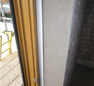
Early parging (plastering) of the window reveal at a Passivhaus retrofit in South Ealing.
Airtightness and structure: floor-to-wall junctions
There can be particular conflicts between the airtightness layer and load-bearing elements. In typical constructions, beams and joists can penetrate the wall structure (bearing their load on to the walls), but once you are in low-energy design mode these penetrations will tend to interrupt the airtightness layer, and you need to ensure that the layer is maintained across the junction. In new builds, the most common approach would to pre-wrap the floor end with an airtight membrane. This can then be taped above and below the floor to the wall airtightness layer. In timber-frame houses, the floors can be pre-made off-site as a single element or cassette. The roof-to-wall junction can also be simplified in this way, using a similar cassette system.
The earlier you look at any such potential sequencing conflicts, the cleaner and simpler solutions are likely to be on-site.
On-site communication, site structures and on-site training
As with the installation of the airtightness layer, unusual sequencing requires clear communication with all on-site workers, and it is important that this happens at an early stage. Different trades will be carrying out work in the same location at different times, and it can be quite demoralising to see your good work undone by another trade that did not appreciate either a sequencing or airtightness factor! Practical face-to-face communication is probably more effective with on-site workers (not relying solely on drawn information), especially as operatives are being asked to alter some of their usual working patterns, and at least initially are being slowed down – and naturally there will be some resistance to this.
Again, independent adoption of the principles of low-energy construction by the site workers is so important – a professional can never predict every consequence of a construction detail, especially any practical restrictions that might be involved. Intelligent problem-solving on-site is an invaluable skill, as long as it involves appropriate communication with the team before implementation. A full briefing of site workers is an important part of this empowering process.
As noted in Chapter 4, in the UK there are fewer and fewer trades employed directly by construction companies. Most tradespeople are self-employed and move from site to site as work becomes available, working either directly for a client or indirectly for a larger building company but on a self-employed basis. Electricians or plumbers, for example, will of course be very focused on their own element of the work and will have limited interest beyond this, especially if on a fixed price. The people they are working alongside will be continually changing as they move from job to job. In these circumstances, it is very difficult to introduce non-standard practices or to build up strong team working. This reality has to be faced honestly and then actively managed.
In order to address some of the communication issues already highlighted, we feel it is essential to include some on-site training; this can be a respectful way of engendering a team approach. It should give those working on the project a basic overview of ultra-low-energy principles so that the reasons for unusual sequencing or different detailing are clearly understood, along with the potential consequences of ignoring them. It is important that the implications of not delivering a contiguous air tightness layer are understood, including serious material degradation through moisture ingress and potential mould growth within the fabric, which can affect indoor air quality (see Chapter 10). Building to ultra-low-energy levels creates a different internal environment, which needs to be properly appreciated. People will be much more likely to change working patterns from a place of understanding than from being given disconnected (and what may seem superfluous) instructions.
Training needs to address both plumbing and electrical penetrations of the airtightness layer. When pricing for the job, both these trades need to understand what is required of them in this regard. The airtightness details are not in themselves difficult, and making penetrations airtight is relatively straightforward if carried out at the correct stage – again, sequencing needs to be understood from the start.
Governments have continued to introduce increasingly demanding legislation in many areas of our lives, but at present such low-energy building legislation remains at discussion/draft stages. Currently there is no access to free retraining either – for builders, architects, planners, building control officers, etc. (The limited training opportunities for construction workers are described in Chapter 4, pages 48-9.) In these circumstances, low-energy projects are likely to continue to be mainly generated by enthusiasts – but not all those working on such projects are likely to be as enthusiastic! Experience demonstrates that being offered intelligent explanations appeals to the majority of those who want to do a good job, who will enjoy learning (and being challenged) and who will then reap the satisfaction of a higher-quality build. If, however, people are frustrated with poor organisation and abortive work, that goodwill can soon dissipate. Good project organisation, clear communication and the provision of some training are the three most helpful tools in getting site workers fully on board.
Airtightness testing
An airtightness test requires some basic kit – a digital pressure gauge, a calibrated fan and an airtight door panel (see photo on page 125) – and the test needs to be carried out by an accredited person. In a typical house, a minimum of half a day is needed for a test to be carried out, including setting up, testing and checking the fabric. The airtightness test result will be affected by high winds, so wind speeds on the day need to be below 6m/s or 21.6km/h. The final test result is an average reading taken under pressurisation and depressurisation; the average must be below 0.6ach.
A minimum of two tests should be allowed for in the build process, but the ideal is to budget for three tests at domestic scale, especially if you are unfamiliar with achieving airtightness at this level. The first test would occur as soon as the external envelope is weather-tight and the doors and windows are installed. This can enable testing of a timber frame prior to any service penetrations, and allow early payment of this package of work, should it be a subcontracted element. The second test would occur once all service penetrations are complete but the airtight layer is still exposed. The final test is of course carried out on completion. The first two tests are opportunities to check that everything is performing as intended; mistakes can then be highlighted and any remedial action taken (obviously this is only true within certain limits). Once the team is practised at achieving airtight constructions, two tests should be sufficient.
Before the test, ensure that any intended leakage paths are sealed, e.g. ventilation units (seal off with tapes) and drainage traps (fill with water).
Gaps in the airtight layer are generally identified using smoke (e.g. smoke guns, pencils or tubes), although a thermal imaging camera can be useful in winter, if available. Under pressure the smoke provides a dramatic illustration of the leakiness potential, and will stream out of the building through any gaps! Of course you can always take the low-tech approach and use your hand (especially the back of the hand). As an example, on one test a single hole in the vapour barrier had not been taped after the roof void had been filled with wood-fibre insulation – the hole was where the pump nozzle had been inserted. This sort of error is exactly the type that can be quickly and effectively resolved at minimum cost. The pressure test is therefore an essential tool and must be carried out prior to any covering up of the airtightness layer.
For larger projects, the contractor might feel that a small airtightness quality control unit would be a cost-effective purchase. This is a smaller, lighter and uncalibrated version of the fan unit from a full testing kit. It is not able to give test results, but will be invaluable in testing areas as the work progresses, and is also a useful learning tool.
Typical airtight construction details
The images on the following pages show a range of common airtightness details, covering both retrofit projects and new builds. Once the principles of airtight construction are understood (by the whole team, and especially those on-site) it is relatively straightforward to amend and tweak these examples to suit the specifics of each individual project. Finding robust solutions is the key – membranes and tapes can get damaged, especially if they remain exposed on building sites for lengthy periods before being covered up.
Externally applied insulation, retrofit detail
Externally applied insulation on a masonry wall around a window frame. Joints should be staggered by 20cm so that air penetration is limited. Fill joints with supplied foam filler, and ensure the use of thermally broken anchor fixings.
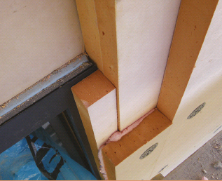
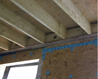
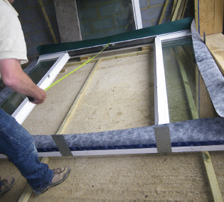
Junction between timber floor and masonry wall, retrofit detail
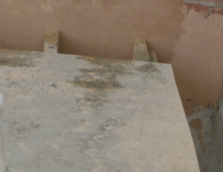
1. Initial plastering (parging) of the floor void between the floor joists – the airtight layer is the gypsum plaster. This is non-standard practice; in a conventional build this void is left as bare block or brickwork.
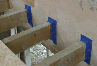
2a. Joist ends are taped to initial plaster (parge) coat. Any dusty surfaces are prepared with a suitable primer prior to applying the airtightness tape. The final plaster layer is applied over the tape to complete.
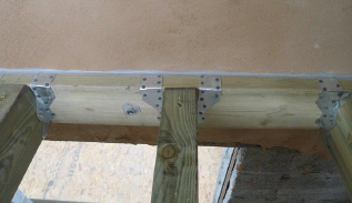
2b. Alternative detail to 2a, with the integrity of the continuous plaster layer maintained by using a timber plate bolted through the plaster into the structural masonry wall using resin-bonded anchors. Floor joists can then be hung off the wall plate in a conventional manner using metal joist hangers. Plate edges can be sealed using airtightness sealant for the extra-cautious!
2c. Alternative detail to 2a or 2b, using a steel beam, which sits on the two party walls and allows all the timber floor joists to be trimmed short of the cold external masonry wall. The steel is also airtight, so could form part of the airtightness layer.
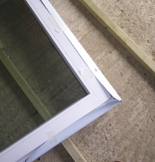
A. Solution using only tape (the usual method described for windows or doors)
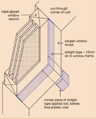
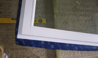
1. Airtight tape is stuck to the face of the frame prior to fitting, using a tape with double-release papers – normally a width of 10mm can be released first to stick on to the frame. Mark the 10mm around the frame with a pencil – overtaping may cause you problems later when trying to cover up the tape with the finishing layers of your window reveal.
2. Tape is temporarily fixed back so you can fit the window easily (use masking tape or similar). Once fitted, you can release the second paper and adhere the tape to the airtight layer of your wall, e.g. pre-plastered (parged) window reveal or OSB.
3. Airtight tape is adhered to the window reveal around the perimeter of the window frame, using primer where dusty to ensure airtightness.
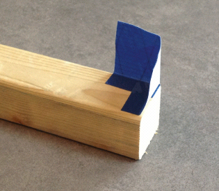
4. Once the window is fitted and the other perimeter tape has been stuck down, you need to form and fit tape corner pieces. This photo shows a mock-up of a separate corner piece of tape on a spare piece of wood. Origami skills are useful here these corners are the likely weak points with this approach. Again, the tape should extend no more than 10mm on to the frame so it can be covered at the final stage. We would suggest at the end applying some Orcon F® glue (or similar) in each corner, just to be quite sure of airtightness. The alternative is to use a membrane around the entire frame, as outlined in option B, right.
Airtight tapes and windows
B. Solution using membrane and tapes (this might be a more robust and flexible approach – especially for doors)
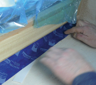
1. Initial stapling of the membrane to the window or door frame. The membrane is then taped to the sides of the frame with airtight tape.
2. Metal ties are screwed into place, ready for lifting up into the prepared wall opening. Once in position, the membrane can be taped around the opening to the airtight layer (whether masonry or timber) at a point to suit the build sequencing.
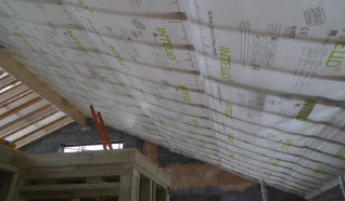
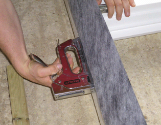
1. An intelligent vapour membrane used as the airtight layer on a timber roof, stapled frequently to the timber roof joists and then taped between adjacent sheets. Ideally fix the timber battens (to form the services void) directly over the taped junction for a very robust detail – as shown below.
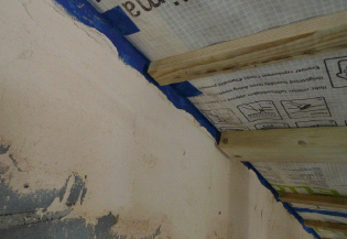
2. Junction with masonry wall. Proprietary fleecy tape is stuck to the vapour membrane and the fleece embedded into the plaster on the wall. Leave some slack in the membrane in case of future movement.
Roof ridge detail
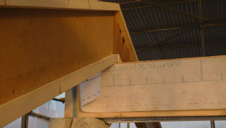
Sequencing of work is often key, and at the roof ridge the airtight layer must be continuous under the ridge beam. Allow for the early installation of a section of the airtight layer, and protect it from damage during construction by covering with a layer of ply. As a rule of thumb, fixing with nails is generally acceptable if fixing timber into timber.
Use of airtight grommets
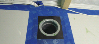
Proprietary airtight grommets: Above: for exit point of ventilation duct; grommet then taped around its edge to the gypsum plaster wall.
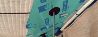
Below: for cables through the airtight membrane.
Passivhaus sets the most stringent airtightness standard in the world, 0.6ach at 50Pa, and this is applied alongside the use of mechanical ventilation with heat recovery (MVHR). The current zero carbon airtightness standard of 3m³/hr/m² leaves the door open to natural ventilation strategies, with significant energy penalties. Reducing air leakage is key to the Passivhaus approach for several important reasons:
• As air leaks out of your home, heat energy is also lost.
• Air moving through your insulation through gaps etc. reduces its effective performance.
• As air moves through your construction (walls, floors and roofs), moisture is also carried into the structure and this can have negative consequences, especially for material degradation (and mould may also affect indoor air quality [IAQ]).
• Low air permeability is essential for a mechanical ventilation system to operate efficiently.
• Reduction in draughts increases comfort levels.
The materials used to ensure airtightness can be breathable, i.e. vapour-open, and still achieve fantastic airtight results. Using such materials can help to contribute to a healthy IAQ.
Non-standard sequencing is likely to be required on-site to maintain the integrity of the airtight layer, which must be unbroken. Early identification of any sequencing issues is important. An airtightness test is needed prior to covering up the airtight layer and is invaluable in identifying small leaks; some remedial work is then possible, and at much lower cost than if left till later.
Achieving airtight construction on-site is a challenge both in terms of general building culture and also because it needs to be supported by appropriate training. If the principles of airtight construction and sequencing are communicated successfully to the site team, it can provide both an enlivening experience and a positive challenge that the contractor can grasp with both hands! Because airtightness is a physically tested quality, success can be a real source of pride for the construction team. While the architect contributes to setting up the airtightness strategy, it is the construction team that has the real task and challenge of meeting this significant part of an ultra-low-energy build.